
MIOConsole3d
v. 6.2.01 Release Notes
This is a bugfix update to v.6.2. It contains the following changes:
- Bootstates saved by the firmware included with the 6.2.01 console corrupt USB when restored; this caused USB connectivity to fail for units with old boot states.
This firmware update changes the compatibility version of the boot states, disabling old states that will cause a problem.
- Under certain circumstances, the mapping config could cause a crash. This build removes those conditions.
- Attempting to set mappings for the Monitor Controller after mappings were created and restored after relaunch,
when the Monitor Controller configuration was loaded from global prefs rather than the cnsl3d file would lead to
corrupted UI and eventually a crash. This build fixes that.
- Make the targets for Talkback and Listenback be parameter targets rather than command targets, so that Set/Toggle/Momentary can be used
Detailed changes since release/6.2.00: (11 commits)
- FEATURE: Add genericTargets for Talkback and Listenback to the talkback controller in the model, with serialization support
- FEATURE: Add GenericParameterTarget that models an assignable on/off target
- BUG FIX: Switch Talkback and Listenback controls to use the state based Targets so that they support set/toggle/momentary modes
- BUG FIX: Correctly have aux send pan follow strip pan when aux send is set to post fader
- BUG FIX: Do not clear existing parameter targets when loading MC config, as the UI may already have references in the case of load from global file. Just re use existing.
- BUG FIX: Ensure that we return empty list rather than list of null targets + add guard to avoid crash
- BUG FIX: Add guard to avoid crash in mappings list window if currentTargetList contains nullptr
- BUG FIX: Firmware bump snapshot version number, as old snapshots are interfering with USB
MIOConsole3d
v. 6.2 Release Notes
This release provides numerous new features and bug fixes, and is a recommended
update for all users. This version has been tested on macOS Sonoma (macOS 14.x),
as well as previous macOS releases.
Table of Contents
- Firmware updates
- Support for syncing ULN-8/LIO-8 Front Panel (FP) Cans Gain with Cue controls
- Ensure 2882 HW Mute/Dim reflects changes from MIOConsole
- Ensure 2882 Front Panel Mute/Dim notifies MIOConsole
- Fix ULN-8/LIO-8 Front Panel link support to properly allow linking output gains
- Ensure all router meters run, even when routing max channels
- Support for Sonic 303 configuration
- Driver updates
- Fix MHLinkServer crashes for corner case issues
- Fix a race condition that can cause a MHLinkServer crash
- Make audio start synchronous to avoid start stutter with some hosts
- Expanded safety offset range
MIOConsole Changes
MIDI Learn & External Controller Mapping Support
The big news in this release is a suite of features added to provide flexible
support for user-defined mapping of external MIDI controllers to virtually
every aspect of the system.
We have added extensive instrumentation throughout to support binding of
external controllers to specific controllable elements of the system.
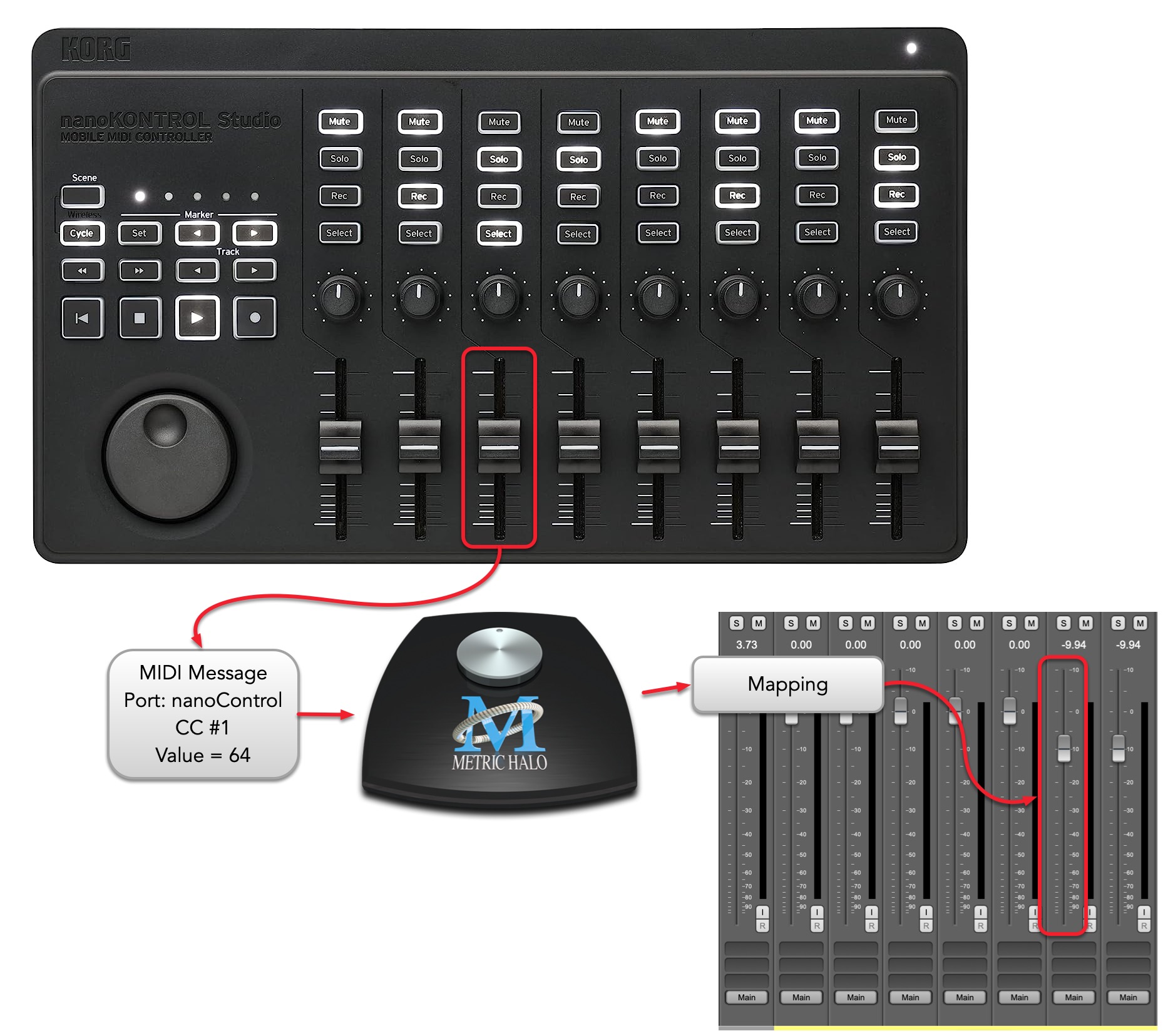
This release of MIOConsole3d adds support for mapping external MIDI controllers.
The architecture of the mapping system was designed to enable support of multiple
external controller types (such as OSC and Front Panel User Mode in addition to
MIDI) and we plan on adding support for things like OSC in the future.
Definition
Mapping: A software connection between the messages sent by
a physical control on an external device or any virtual device that can
generate MIDI messages (e.g. via Network MIDI or CoreMIDI IPC MIDI channels)
and changes to a specific virtual control in the system.
Mappings are represented in MIOConsole as
a set of filters that restrict the response to messages of the specific
type emitted by the external controls.
Mappings can be made between external controls and the parameters, commands
and various UI elements in the software.
This mapping system differs from MIOConsole3d’s existing support for EuCon and
Mackie Control Protocol based control surfaces (also known as Control Surface Support).
Both the new mapping system and the existing Control Surface Support run in
parallel with each other, and any or all of the external control systems can
be enabled and active at the same time.
The Control Surface support dynamically assigns physical controls from
surfaces with well known layouts to the various supported virtual controls in
the system (with support for paging and nudging, and context sensitive control
modes).
The mapping system aims to provide a different capability.
Rather than having
a dynamic mapping based on the control surface layout and Metric Halo’s mapping
choices, the the new mapping system provides the user with the capability of
making fixed mappings between arbitrary external controllers and specific
parameters and/or commands in MIOConsole3d on the fly.
While you use the GUI to easily select what parameter or command you want to
map to, the bindings you create are not dependent on the UI, so they remain
active even when the UI is not on screen.
For global elements of the system (eg. Monitor Controller, Cue Controllers,
Transport, Key Commands), this fixed mapping is quite natural. For more dynamic
elements of the system (eg. strips, busses, plugins) the fixed mapping may feel
limiting or surprising.
Think of it like a mapping for performing with a specific setup
(performing in the generic sense, as this could just as easily apply to mastering
as it does to performing on stage). You associate a fixed control on your external
surface with a fixed element in the system.
It allows you to build a dedicated fixed-knob-per-function control surface for
the processing in your setup.
Utilizing the Used Future
Since the system utilizes virtually any MIDI message for control, you can take
advantage of the wide variety of MIDI controllers most users collect over the
years.
No Controllers, no problem
If you don’t have any MIDI controllers available in your personal
inventory of gear, there are a huge number of different MIDI controllers
readily available from different vendors and many of them are very inexpensive
with direct USB connections. So pretty much whatever generic MIDI controller(s)
you choose, it is plug and play.
Mapping in Practice
Mappings can be established in one of two ways:
- Per-control assignment
- Auto-assignment mode
Per-control assignment: This is initiated by typing ⌘1 (Command 1) while hovering
the mouse over the control that you want to map to.
The control you are hovering over can be any on the list below, or the name
of a command in the command-keys window.
When you press ⌘1, an assignment window will popup pointing at the control.
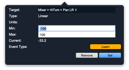
If the control doesn't have a mapping, the assignment window will
automatically be in Learn mode (e.g. the Learn button will be illuminated).
While in Learn mode, you can trigger a MIDI message by touching a button, key
knob, expression controller or the like on the external MIDI controller, and,
the assign window will capture the message and set up the mapping for you.
You can finalize the mapping by clicking on the Set button (or press the
return/enter key), or you can further edit the mapping parameters using the
controls in the assignent window before finalizing the mapping.
If you want to cancel the mapping rather than finalizing it, you can
click the Remove button. This can also be used to delete an existing mapping.
If the control already has a mapping, the Learn button will be light grey
and the message parameters will be listed at the bottom of the assignment window
like this:
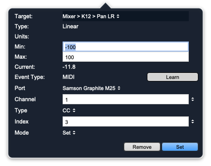
If there is a mapping present, you can either edit it via the controls in the
assignment window, or you can click the Learn button to enter Learn mode (as
described above).
If the UI item you are hovering over when you press ⌘1 has multiple parameter
targets associated with it (for example a surround panner, or an aux send control),
then all the available parameters will be in the “Target:” popup menu. You can
click on that popup to switch between the available targets:
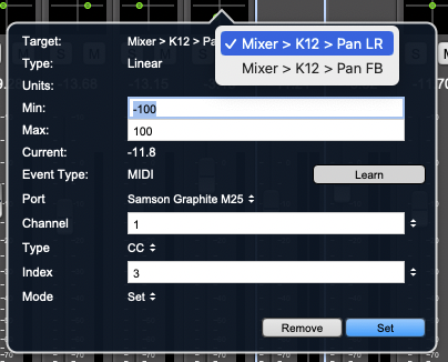 If you select a new target, the current controller filter will be saved for the
target you are switching from (as if you had clicked the Set button); this allows
you to press ⌘1, touch an external control to assign the first target of the UI control,
then use the popup menu to switch to the next target and repeat the process, clicking
the Set button once you have set the controllers for all the targets you wish to
assign.
If you select a new target, the current controller filter will be saved for the
target you are switching from (as if you had clicked the Set button); this allows
you to press ⌘1, touch an external control to assign the first target of the UI control,
then use the popup menu to switch to the next target and repeat the process, clicking
the Set button once you have set the controllers for all the targets you wish to
assign.
The following MIDI messages are supported:
- Note On/Off
- CC (7-bit)
- Aftertouch
- Program Change
- Channel Pressure
- Pitch wheel
- SysEx
By default, the learned mappings filter MIDI events to the specific message
from the specific port that the learned message was received from. So if you,
for example, learn CC#0, on channel 2 of Port "Sampson Graphite M25", even if
you send a CC#0 from a different port, or even the same port on a different channel
the filter will treat it as a different controller.
However, you can if you choose
set the various filters to "Any", and if a given filter is set to "Any", then the
mapping will trigger as long as the rest of the filters match. So you could set the
port to "Any", and then any CC#0 on channel 2 would trigger this mapping.
For each message, the following processing modes are available (although some
messages and/or targets only support a subset of the processing modes):
- Set Value: Set the value of the underlying parameter based on the value in the message
- Toggle: Toggle parameter on/off each time the message is received (works best with Note/Program Change/SysEx)
- Momentary: Turn parameter on/off on press/release (works best with note messages)
- Trigger: Fire associated command (Note/Program Change/Sysex)
- V-Pot: Only for CC; CC must use Mackie Control Protocol V-Pot encoding
The system will attempt to select the correct processing mode automatically,
but you can set it via the "Mode" popup menu in the Assignment window.
Each mapping also includes a user-configurable range for mapping the external
controller value to the underlying parameter's value when the Mode is "Set".
The Min setting will be the value used when the external controller is set to its minumum value. The Max
setting will be the value used when the external controller is set to its maximum
value, and in-between values for the external controller will interpolate between
the user specified min and max (using the parameter's built-in taper) for the underlying
parameter.
Note: You can set the min to be larger than the max, and this will
have the effect of inverting the sense of the parameter.
This user-defined range mapping can be used to good effect to do things like:
- Limit the range of a control - for example, map a subset of MC gains to
a MIDI CC
- Invert a control (e.g. turn a bypass into an enable or vice versa)
- Stagger or offset ganged controls
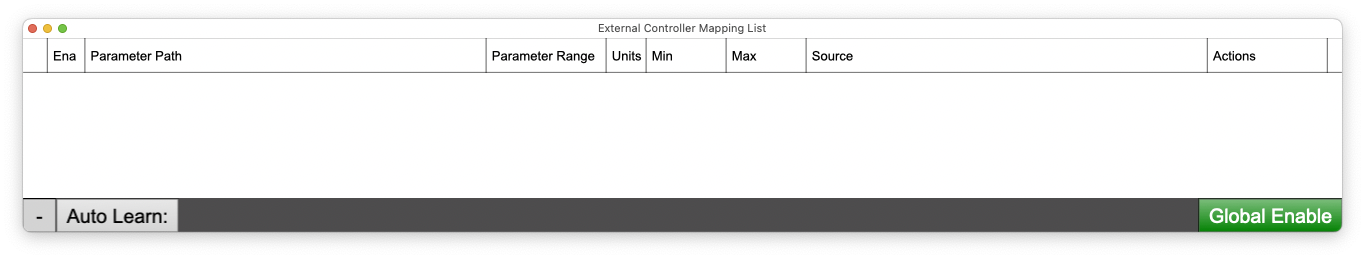
We have added a new window (External Control Mapping List) that shows all of
the defined mappings in the system; when there are no mappings defined, it looks
like this:
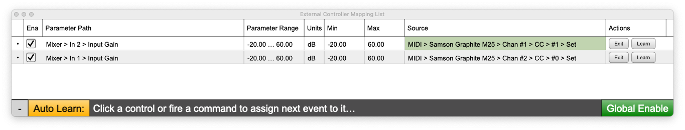
After you define a mapping (e.g. via ⌘1 or the Auto-assignment mode below),
the mappings will be added to the list:
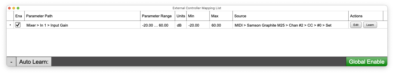
You can sort the columns by clicking on them, (Ena, Parameter Path, Source). You
can edit a mapping directly from the list by clicking the associated mapping button,
or you can relearn the mapping directly via the Learn button. The Enable checkbox
allows you to disable (or re-enable) the mapping without removing it. The Min and
Max columns in the table are editable directly from the table without having to
invoke the mapping editor.
Finally, you can delete a mapping in one of the following three ways:
- ⌘1 or click the Edit button, and click the Remove button
- Right-click the dot in the left most column and select Delete Row
- Click and then command or shift click the dots in the leftmost column to select multiple rows,
and then click the – button in the bottom left hand corner of the window
Auto-assignment mode: This is initiated by typing ^2 (Control 2). The External
Controller mapping list window will be shown if it was not already visible and
the Auto Learn: button in that window will turn yellow.
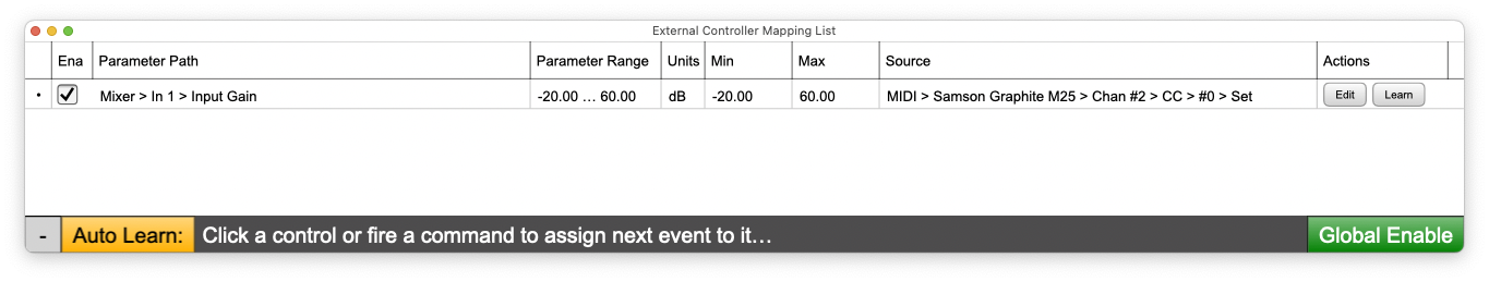
As you touch controls or fire commands in the MIOConsole3d, the text next to the button will be updated to
reflect the current command/parameter that will be mapped on the next MIDI message.
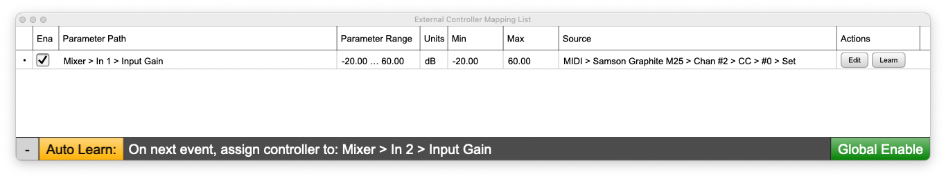
When the next MIDI message is received, it will be mapped to the current parameter
(as if you used the per-control assignment mode, and immediately press the Set button
after the MIDI message is received).
You can then touch another control, and send a MIDI message to map it,
and repeat as desired. When you are done mapping controllers, you can click the Auto Learn:
button or press ^2 again to toggle off the auto-learn mode.
Note: When an external controller’s message matches the filter assigned to
a target the associated “Source” field in the External Control Mapping List will
flash green to let you see that the messages are being received and matched.
The green Global Enable button in the lower right corner of the
External Control Mapping List window is connected (and synchronized)
with the Global Enable External Mapped MIDI Controllers menu command.
When the button is green, the mappings are active and will respond to messages.
When the button is light grey, the mappings are globally disabled. You can
use this to turn off all the mappings without having to delete them or disable
them individually.
Multiple Mapping
Each parameter or command can only have one external controller mapped to it,
but any external controller can be mapped to multiple parameters, so you can control
more than one parameter with one external controller.
In addition, each mapping can have an independent processing mode, and can
also have a different mapping range. One useful thing you can do is set on/off
controls to have opposite mappings with one external source. This allows for
arranging multiple bypasses or enables to be operated in opposition to each other
with one CC or note controller.
New Menu Commands
There are four new menu commands in the Edit menu that relate to external
controllers:
- Assign Controller for item under mouse… - Default key command: ⌘1 (Command 1)
Displays the Controller assignment window for the control that is under
the mouse pointer when the command-key is pressed; not very useful as
a menu command, but it is in the menu to make it easier to see the
associated command key.
- Auto Learn Controller for last parameter - Default key command: ⌃2 (Control 2)
Toggles Auto Learn mode on and off.
- Show/Hide External Controller Mapping List Window - Default key command: ⌃3 (Control 3)
Toggles the visibility of the External Controller Mapping List Window.
- Global Enable External Mapped MIDI Controllers - Default key command: ⌘⌃M (Command Control 3)
Enables (when checked) or Disables (when unchecked) responding to MIDI mappings.
You can use this to temporarily disable all MIDI mappings without having to delete
them or disable them individually. This item is checked by default, and is stored
as an application-wide preference (and not as parameter of the .cnsl3d file).
The elements that can be controlled are:
- All mixer strip parameters for Input, Bus, and DCA strips including:
- Fader Gain
- Pan
- Mute
- Solo
- Record Enable
- Input Enable
- Preamp Gain
- Polarity Invert
- Phantom Enable
- Insert Bypasses
- Hard Mute
- Aux Send Gain
- Aux Send Pan
- Aux Send Mute
- Aux Send Solo
- Mixer Scroll Bars
- Mute Group Enables
- All Plugin Parameters
- Plugin Bypasses
- I/O Insert Bypasses
- Graph Insert Bypasses
- Sub-Graph Bypasses
- Monitor Parameters including:
- Monitor Gain
- Input Source
- Output Destination
- Monitor Graph Bypasses
- Speaker Mutes
- Mono
- Mute
- Dim
- Cue Parameters including:
- Cue Gain
- Cue Input
- Cue Graph Bypasses
- Mono
- Mute
- Dim
- Talkback Enable
- Listenback Enable
- Session Related:
- Transport Controls
- Play
- Stop
- Rewind
- Record
- Pause
- Loop Playback Enable
- Metronome Enable Toggle
- Grid Enable Toggle
- Fit Tracks Vertical
- Fit Tracks Horizontal
- Horizontal/Vertical Zoom
- Horizontal/Vertical Scroll
- All Commands listed in the Edit Key Commands window
The elements that can not yet be controlled are:
- Input and Output gains in the Analog I/O window
- Strip Selection
- Headamp input mode
- Internal Sample Rate
- Clock Source
- Link group Enablement
- Strip Input Source
- Strip Direct Out Destination
- Mix bus output assigns
- Strip to Bus assigns
- Cue controller dim levels
- Talkback Input gain
- Playhead position
- Recording mode controls
- Digital I/O Output mode controls
- Preferences
New Plugins
The Quad Modulation LFO plugin provides an analog-synth style
multi-waveform LFO generator:
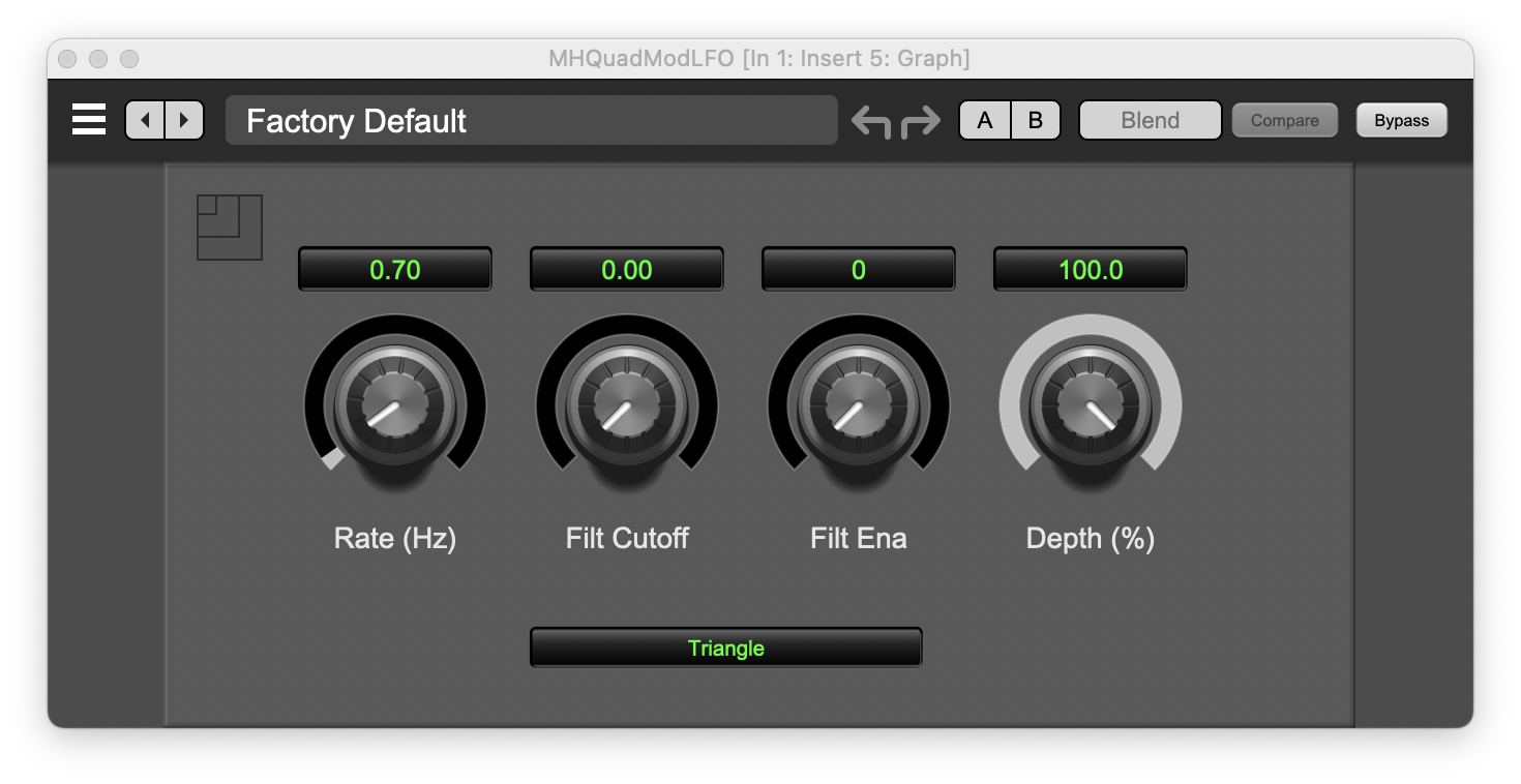
This signal generator creates a low-frequency waveform (0 - 20 Hz). The two
outputs of the plugin are in quadrature (e.g. one is 90° phase shifted from the
other).
The signal generator can create the following waveforms (selectable from the
popup menu). These waveforms are not bandlimited when the filter is not engaged.
- Triangle
- Sawtooth
- Sine
- Square
The frequency of the generated signal is controlled by the Rate parameter.
The signal generator also includes a Low Pass Filter. The filter can be used
to shape the waveform and smooth the sharp transitions.
The Filt Ena
parameter controls whether the filter is on or off. The Filt Cutoff parameter
sets the cutoff frequency of the filter in Hz. If you set the Filt Cutoff parameter
to 0 Hz, the plugin will automatically make the filter cutoff frequency track the LFO
frequency.
Finally the Depth % parameter controls the magnitude of the waveform.
Plugin updates
The plugins included in the 3d system have received significant updates. Most of
of these updates apply to all the plugins in the system
(Undo/Redo/Snapshots/Blend/Controller Support), but the Sontec MES-432D9D has
received many plugin-specific updates.
Sontec MES-432D9D
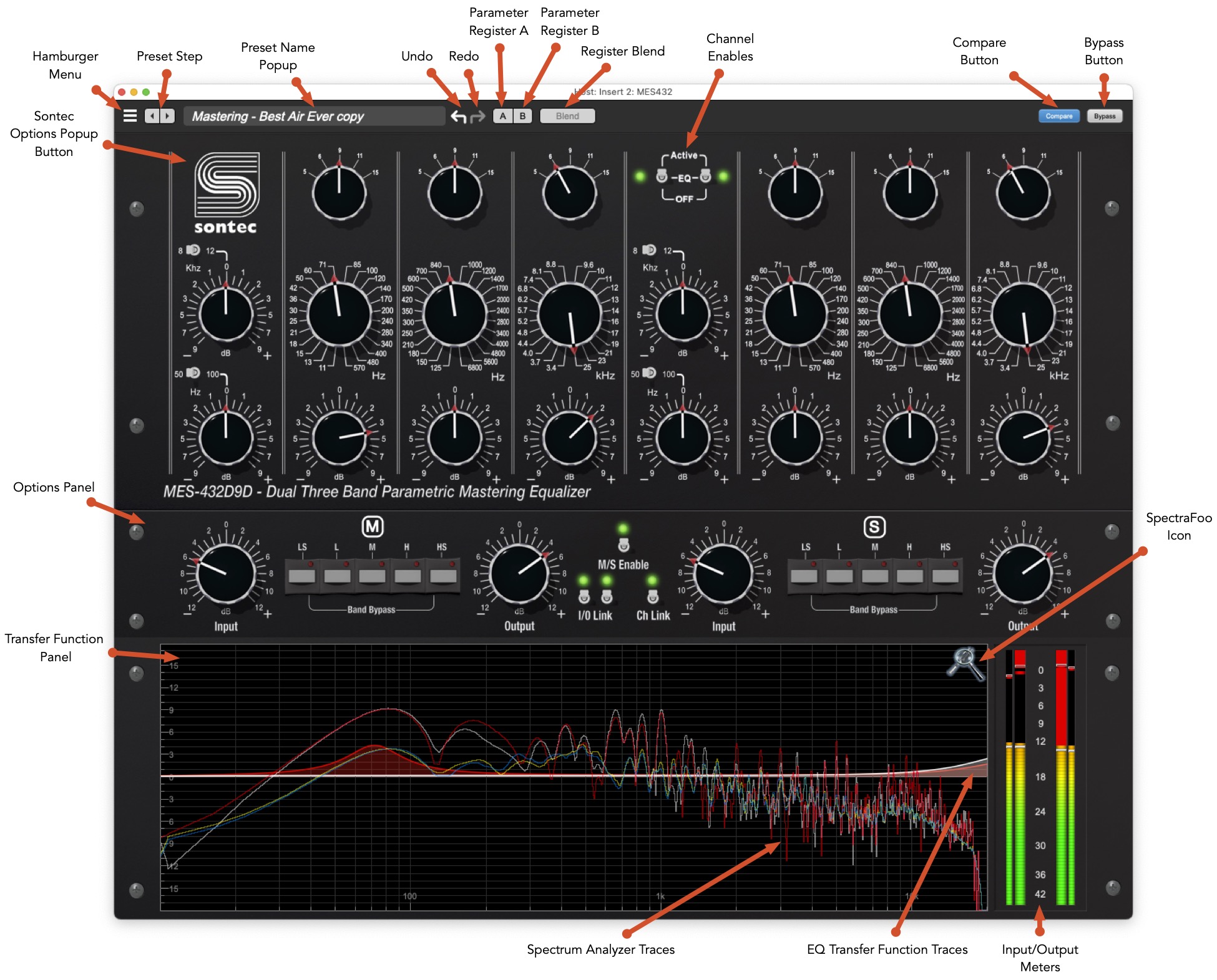
This release of the Sontec MES-432D9D adds an Options panel, which provides access to some of the most requested features in a friendly and easy to use layout.
The new features include:
- Per-channel Input gain control
- Per-channel output gain control
- Per-band bypass
- Mid/Side EQ mode
- Input gain link control
- Output gain link
- New channel linking features (explicit control, offset linking)
These new features allow you to fine tune the equalizer to your particular workflow.
When in mid-side mode L/R input gain becomes M/S input gain, but the output gain remains left and right.
The knob controls in the UI have many gestures available to support alterate modes
of operation. Many gestures were already supported in the previous release, but there
are new gestures that have been added. The comprehensive list of gestures supported by this release are:
- Right Click (or <control>-click) on any knob to type in a value for the parameter. Note for stepped parameters, the value will snap to the closest available step. The text entry field will interpret suffixes so you can type either 1.2k or 1200 for 1.2kHz, for example.
- Mouse scroll wheel over a knob will increase or decrease its value (depending on the direction of the scroll wheel. You can also hold the <command> key to go into fine-adjust mode for the input and output gains.
- <option> click on any knob to reset it to the default value.
- <command> click for fine-adjust mode - this only applies to the input and output gains, as all the other controls are stepped.
- <control><option> click on any knob to reset it to the minimum value.
- Hold the <shift> key to defeat linking between channels for the parameter while you are changing it.
- <shift><option> to reset the parameter while leaving the linked parameter from the other channel alone.
- <control><shift> on input gain to reciprocally change the output gain; this allows you to adjust the drive level into the analog processing without changing the overall output level through the processor.
- Double-click band gain knobs to toggle the associated band enable state. When a band is disabled, the gain knob for the band will become translucent indicating that the band is not processing the audio.
The Transfer Function panel allows you to see the transfer function of EQ based on the settings you have made. Since the MES-432D9D supports unlinked operation, the transfer function displays the curve for both channels when it is unlinked:
- When the channels are fully linked the gain curve is displayed with a red fill.
- When the channels are not fully linked, the Left (or Mid) gain curve is displayed with a red fill, and the Right (or Side) gain curve is displayed with a white fill.
The SpectraFoo logo (the tuning fork+magnifier) in the top-right corner of the transfer function controls the display of the analyzer. You can -click the SpectraFoo Logo to popup the Analyzer Options menu:
- Dim Analyzer Traces - on by default, this makes the analyzer traces less prominent in the display. Turn this off to make the traces bright.
- Show Instantaneous Trace - shows the spectral content of the signal with no averaging. This lets you see narrow and short lived features. It is useful for being able to see the signal content of impulsive sounds.
- Show Average Trace - shows the spectral content of the signal with averaging. This gives you a time averaged view of the signal and lets you see the overall tonal balance of the material while averaging out short-lived transient events.
Input/Output Meters
The meters are displayed to the right of the transfer function in the transfer function panel. The meters include Peak Hold (held red bar), PPM (floating bar), VU (floating grey bar) and RMS (solid bar). Click to reset peak holds and clip indicators.
Inputs are smaller meters to the outside, outputs are larger meters in the middle. This adjacent layout allows you to adjust output gain to level match Output to Input.
Plugin Undo/Redo

All the plugins now provide support for undo/redo from the plugin header bar.
The left and right curved arrows represent Undo (Left) and Redo (Right). These arrows are grey when there is nothing to Undo or Redo.
The arrows are white when it is possible to Undo (Left) or Redo (Right). Clicking the left arrow when it is white will undo the last action you made in the plugin. When you undo something that change is placed on the redo stack, and the Redo button will turn white.
Clicking the Redo button (when it is white) will restore the state that the last Undo changed.
If the Redo button is white, and you make a change in the plugin, the Redo button will go grey as the redo stack will be cleared.
Plugin snapshot registers: A/B
The A and B buttons control the A and B state registers. For each of the A and B buttons the visual display tells you the state of the register:
- Light Grey means it is empty
- Dark Grey means it has settings, but is unselected
- Blue means it has settings and is selected
You can perform the following actions:
- Clicking on an empty register sets it to the current settings
- Clicking on an unselected filled register sets the current settings to those that are in the register
- Clicking on a selected register toggles to the other register; this lets you toggle between the register settings without having to move the mouse
- <option> clicking on an register sets it to the current settings
- Changing settings when a register is selected will change the settings in the register
Snapshot blend
The Blend button’s visual display tells you the state of the register:
- Light Grey means it is empty
- Dark Grey means it has settings, but is unselected
- Blue means it has settings and is selected
The Blend button allows you to interpolate between the settings in the A and B registers.
It becomes active when both A and B have a setting stored.
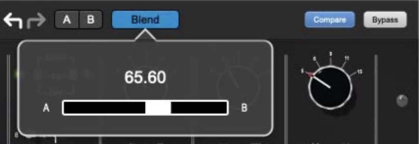
Click on the Blend button to popup the blend control. Slide all the way to the left to apply the settings in the A register. Slide all the way to the right to apply the settings in the B register. Intermediate settings for blend will give you intermediate settings for any parameter that is different in register A and B. The blend control does not change the state of Bypass.
Note that the Blend is not a parallel processing mode where two instances of the processor are running with A and B settings and the output is a parallel blend of the two settings. Rather Blend applies the interpolated settings to one instance of the processor.
Blend is a mappable parameter so it can be controlled with an external controller.
The A/B and Blend settings are stored and recalled as part of the plugin state (but not presets in the preset bar).
While you can use the blend with arbitrary A and B settings we find it works best when you craft the settings in the two registers in such a way as they are related to each other.
Specifically, if an indexed parameter is different between the two settings, the interpolated value will snap to one of the indexes between the two settings, which can be jarring (e.g. Q, MS, Band Enable).
It is best if the parameters that you blend are smooth parameters (e.g. gains, frequencies) and make sure the indexed parameters (enables, modes, band types) are set the same for both registers.
The easiest way to do this is to load the same setting into both registers and then tweak the settings one of the registers.
This works especially well if you make one of the registers be the basic settings with all the gains or thresholds flattened out so that you can smoothly interpolate between a setting and effectively bypassed - we have found that this allows you to zero in a perfect configuration between too much and too little.
Miscellaneous Changes
Most of the changes in this section are small usability enhancements.
Bug Reporter Changes
As macOS has evolved, the places that data is logged by the system has changed,
and relevant data that might bear on problems that you may encounter is now in
different system logs. We have updated the log collection mechanisms in MIOConsole3d
so that the logs that are attached to bug reports you file will be more helpful in
isolating the source of the problem.
Sometimes the logs that have been generated are quite large and, in the past,
oversized logs have prevented bug reports from being processed correctly due to
upload file size limits on the back end server. With this release, MIOConsole3d
automatically detects when a log file is likely to be too big, and automatically
compresses it before uploading to avoid issues in processing the bug report.
Cue Controller Hardware Sync
In previous versions of MIOConsole3d, even when a Cue controller was
connected to an output path that supported direct hardware control over Gain,
Mute, and Dim (e.g. the headphone output on any box for mute & dim, and a LIO-8
or ULN-8 for headphone gain), there was no syncing between changes made in the
Cue Controller and the underlying hardware controls.
Each control UI was independent, and if you made a change via the HW
controls, the GUI would not update to reflect those changes. If you then
touched the GUI controls, the state of the HW would jump to reflect the current
GUI settings.
This release of MIOConsole3d, along with the included firmware update
resolves this disconnect, and now the Cue Controller will automatically follow
changes you make to the Gain, Mute, and Dim via the HW controls, thus ensuring
that everything remains in sync.
Note: This functionality does rely on changes to the firmware, and as
result, will require you to update your MIO firmware in order for the Cue
control sync to work properly.
Graph sub-graph nodes
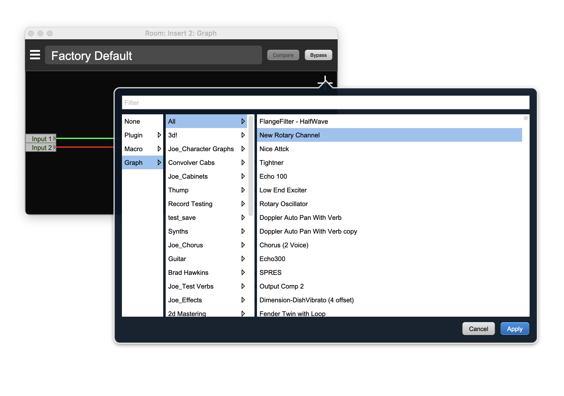
We have added support to the +DSP graph to allow creating or inserting graphs as nodes within the graph. This works any place you can insert a graph (including insert slots, monitor and cue output graphs, and within subgraphs).
To insert a graph inside a graph, just select “Graph” or “Macro” from the insert popup selector. If you insert an empty graph, you’ll get a stereo->stereo graph node. If you insert a Graph preset or Macro, you’ll get a node that has the I/O config of the preset.
To edit the contents of a Graph node, you double-click it, just like a plugin node. That will open a graph window representing the subgraph. As we mentioned above, you can also insert graphs within subgraphs - this can be done recursively.
You can also create a subgraph in-place from a group of selected Nodes within a graph. To do this, select the nodes you would like to push down into the new subgraph node, and then press the “n” key.
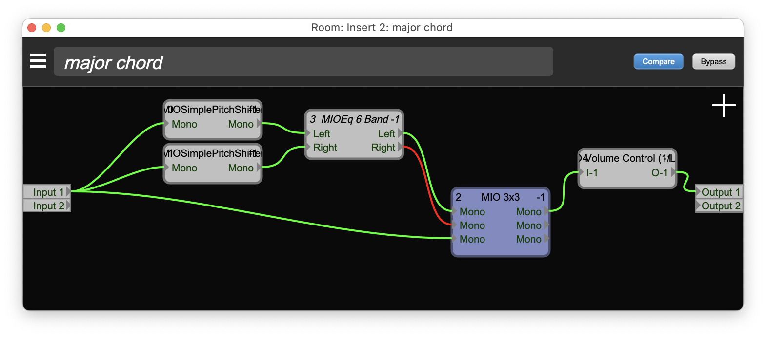
This will move the selected nodes as well as all the connections that are internal to the selected group of node into the new subgraph; it will create an input port for any connection that enters the group from outside the selected set, and it will create an output port for any connection that exits the selected set. The connections entering and exiting the selected set will be connected to the created ports, and the created ports will connect to existing connection points within the containing graph.
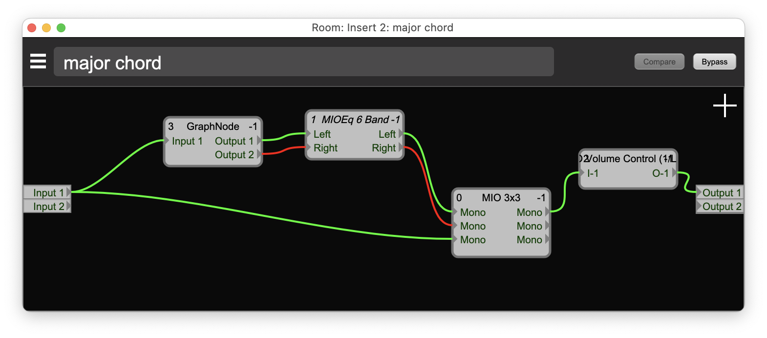
The net effect is that the signal graph will run exactly the same way as before you extracted the subgraph, but the selected nodes will now be within the newly created subgraph.
This allows you to simplify graphs that have become too complicated, and also allows you to build up complicated graphs from a library of simpler subgraphs.
Session improvements
We have added support for a dedicated “Virtual Sound Check” mode to Session to simplify routing.
We have fixed an issue with the display of very long (> 10 hours) sessions.
We have fixed an issue with the display the timeline ruler in long sessions.
Domain management improvements
We have added a command to delete all offline domains at once.
Bug fixes
Please look through the Detailed Change Log for a list of the bug fixes in this release.
New Firmware
We added the support required for the HW to properly notify MIOConsole3d when hardware Gain/Mute/Dim was changed for the headphone output path; this allows MIOConsole3d to keep the Cue controllers that are assigned to
headphone outputs properly synchronized with the the state of the hardware.
The firmware had a bug that prevented defining link groups on analog outputs from the front panel on LIO-8/ULN-8. This was a regression from how the 2d firmware worked, and this issue has been fixed.
The meters in the system are generated as a side effect of the signal routing process in the MHLinkRouter in each unit. Under normal circumstances
this always works correctly, but under heavy load conditions the last few channels routed did not have the meters calculated. This issue has been fixed.
The Sonic 303 is a unit based on 2d that doesn't have an analog board. This version of the firmware adds support for upgrading the 303 to 3d.
Driver Updates
We fixed a rare race condition that could cause a crash in the MHLinkServer process that provides the services to communicate with units over MHLink.
We fixed a rare corner-case condition that could cause either the MHLinkServer or MIOConsole3d to crash under certain network conditions.
We fixed an issue that could cause audio to stutter when streaming began. This issue was only triggered by a subset of hosts, based on how they used the CoreAudio API.
We increased the amount of safety offset you can set using the MHLink CoreAudio Driver Control Window. This is not required (or even desirable)
for most users, but for people recording very large channel counts at very high sample rates, especially on older computers, the scheduling jitter in the OS can be high enough to swamp the previous maximum safety offset of 10ms. For people doing large live recordings, RT latency is not an issue (as the computer is not used for monitoring for talent) whereas absolute safety is. So for this use case, you can now increase the safety offset up to 100ms.
Detailed changes since 6.1.02
Changes since release/6.1.02 (1067 commits)
- FEATURE: keep track of MIDI receivers that have been connected to all sources, and automatically connect to all sources on MIDI system configuration change
- FEATURE: Add support for making the Cue Controller float
- FEATURE: Add "Delete all Offline Domains"
- FEATURE: Add accessors to determine if a source has a filter installed or has received an event
- FEATURE: Add API for determining if a destination is associated with FP cans path
- FEATURE: Add API to allow applying an operation to any existing callout boxes
- FEATURE: Add API to allow client to request rescan of all potential sources
- FEATURE: Add API to allow lambdas for BJJNotifiers
- FEATURE: Add API to update headphone gain for a specific unit in domain + broadcast cue controllers
- FEATURE: Add APIs for explicitly controlling cans mute/dim/gain front panel settings
- FEATURE: Add APIs for guarded access to transformer parameters through MHGenericTarget
- FEATURE: Add APIs to allow host to tell plugins where they are instantiated
- FEATURE: Add APIs to allow MHGenericParameterTargets to report HumanReadablePath
- FEATURE: Add auto assign button to controller mapping window (and couple it to auto assign state)
- FEATURE: Add automation support for snapshot blend
- FEATURE: Add command map for "fitHorizontal" button in the session window
- FEATURE: Add command map for "fitVertical" button in the session window
- FEATURE: Add command mappings to the Talkback and Listenback buttons so we can bind to MIDI
- FEATURE: Add command target for the "Grid:" enable button
- FEATURE: Add commmand code and handler for record pause
- FEATURE: Add compatibility API to allow swapping between DSP peak meter and DSP meter block
- FEATURE: Add control over resizing of graph when loading graph parameters
- FEATURE: Add DrawUndoIcon/DrawRedoIcon API
- FEATURE: Add extension point so MHGenericParameterTarget subclasses can configure automatically on eventSourceChanged
- FEATURE: Add GenericBypassParameterTarget tracking to bypass button in I/O insert
- FEATURE: Add getIdealWidth support to MHPillToggleButton
- FEATURE: Add implementation of MHKeyCommandTarget to support MIDI > Command mapping
- FEATURE: Add InsertRefBypassTarget
- FEATURE: Add MHCommandKeyTargets for the transport buttons and the metronome control
- FEATURE: Add MHGenericParameterTargetHolder support to key commands list
- FEATURE: Add MHUnit API to read both Front Panel Monitor Controller and Cans Dim/Mute state
- FEATURE: Add more tagging to simplify event tracing
- FEATURE: Add notification target to source field of External Controller Mapping window to indicate when a message is triggered
- FEATURE: Add notification when auto assign mode changes
- FEATURE: Add offline convolution support
- FEATURE: Add parameter target binding to bypass button in graph window
- FEATURE: Add pre and post extension points for SetParameter in MHPlugInUI
- FEATURE: Add preference for controlling use of shadow backing image for UI rendering
- FEATURE: Add Quad Modulation LFO plugin to MIOConsole +DSP
- FEATURE: Add RebootAllUnits to Domain
- FEATURE: Add second parameter with boolean state (e.g. for enable/disable) to MHMultiFrameControl
- FEATURE: Add serialization support for Event Source (e.g. MIDI) > Command mappings
- FEATURE: Add snapshot and blend support to MIOPlugIn
- FEATURE: Add Snapshot Support for Plugins
- FEATURE: Add snapshot UI to plugin header bar
- FEATURE: Add sorting support to controller list
- FEATURE: Add source and destination selector parameter targets
- FEATURE: Add support for Return key in mapping window
- FEATURE: Add support for a sort handler on MHPropertyListTableEditor
- FEATURE: Add support for adding pre and post components to status readout bar in property editor
- FEATURE: Add support for archiving and restoring InsertRefBypassTarget
- FEATURE: Add support for attaching to InsertRef for bypass rather than insert slot
- FEATURE: Add support for auto clearing of clip indicators
- FEATURE: Add support for binding controller to session horizontal/vertical scale controls
- FEATURE: Add support for binding controllers to specific MHWidgets
- FEATURE: Add support for building using cmake
- FEATURE: Add support for capturing Sysex
- FEATURE: Add support for changing properties of individual underlying buttons of MHRadioButton
- FEATURE: Add support for clients registering for notifications from MHGenericParameterTargets
- FEATURE: Add support for cloning a MIOPlugInSnapshot with updated properties
- FEATURE: Add support for constant properties in PropertyTable
- FEATURE: Add support for controlling the displayed precision on floating point elements, update build to support this
- FEATURE: Add support for event modes in MIDI Event Source
- FEATURE: Add support for filtering and sine modes for quad LFO
- FEATURE: Add support for getting human readable path components from GenericParameterTargets
- FEATURE: Add support for graphs in graphs
- FEATURE: Add support for inverse input output gain linking gesture (<control><shift> while changing gain)
- FEATURE: Add support for MC instances to track their index
- FEATURE: Add support for MHGenericParameterTarget::handleEvent API
- FEATURE: Add support for next preset/previous preset buttons for plugin header bar and adjust layout
- FEATURE: Add support for no analog (303 like) 3d Card configuration
- FEATURE: Add support for opening generic UI instead of custom UI by holding down option key on plugin UI open
- FEATURE: Add support for pill buttons without background tiles
- FEATURE: Add support for plugin header to report minimum width so that it does not get unusably small, and make hosts respect it
- FEATURE: Add support for processing alternate event modes
- FEATURE: Add support for properties to MHGenericPreset
- FEATURE: Add support for rescan of MIDI system on notification that it has changed
- FEATURE: Add support for serializing GraphBypassParameterTarget mapping
- FEATURE: Add support for setting size of button bar in Property Table
- FEATURE: Add support for stacked extra backgrounds in MHPluginUI
- FEATURE: Add support for virtual sound check mode from Session
- FEATURE: Add support for Widget subclasses to prevent touches from being sent to UI (to support workaround for Logic, but also proper undo)
- FEATURE: Add support to find the frontmost plugin window and front most plugin UI
- FEATURE: Add support to MHGenericParameterTarget for tracking last active MHGenericParameterTarget for auto assign
- FEATURE: Add support to MHPropertyListTableEditor to delegate add/delete actions
- FEATURE: Add support to PropertyListTableEditor to selectively enable add row, delete row functionality
- FEATURE: Add Undo Support for Plugins
- FEATURE: Add undo support to core plugin infrastructure
- FEATURE: Add Undo support to core PluginUI infrastructure
- FEATURE: Allow widgets to update current MHGenericParameterTarget
- FEATURE: Automatically select toggle mode when learning a switch from note, programChange or sysex
- FEATURE: Automatically show Controller List window when entering auto assign mode
- FEATURE: Convolver: Add support to resample impulse to match current processing sample rate
- FEATURE: DRY up serialization code by building common routines
- FEATURE: DSP: Add read support for DSP delay interp mono
- FEATURE: DSP: Add read support for DSP delay mono
- FEATURE: DSP: DSP quad LFO add support for gain, and for wrapping in a plugin
- FEATURE: Ensure plugin graphs track their container location so that parameters in graphs have full context in mapping window
- FEATURE: Expose controller mapping commands in the Edit Menu
- FEATURE: GenericControl: Add support to enable/disable MHGenericEventSource
- FEATURE: Graph: Add captured plugin UI with feature flag (disabled)
- FEATURE: Implement getHumanReadablePath for MHPluginParameterTarget + MHMixerParameterTarget
- FEATURE: Implement PPM/RMS/VU meter as DSP block
- FEATURE: Make PropertyView public so notifier can use it, and add support for owned notification target + trigger background flash
- FEATURE: Make Sontec Menu accessible from any non control area of UI via control/right click
- FEATURE: MHLinkServer: Increase the device buffer size to 65,536 samples, which is 341 ms @ 192k, so that longer safety buffers will fit in the buffer
- FEATURE: MHSpectragraphRenderer: add support for alpha dim
- FEATURE: MHTransferFunctionDisplay: Add support for client to be notified when run analyzer changed
- FEATURE: Plugins: Add preset resources to top level of sources for inclusion in installers
- FEATURE: Plugins: Add support for embedding popups in UI (required for AU with out of process UI)
- FEATURE: Plugins: Distinguish between preset loads and other batch parameter updates
- FEATURE: Plugins: put snapshot blend controller on its own button
- FEATURE: Properly update Cans Mute/Dim/Gain from MC/Cue controllers if target is a headphone port
- FEATURE: Scale up GenericControllerListPane by 25% to make it easier to read
- FEATURE: Serialize and Unserialize parameter targets for MC/Cue objects
- FEATURE: Show last touched parameter
- FEATURE: Sontec: Add Analyzer feature popup menu to allow user to tune analyzer behavior
- FEATURE: Sontec: Add meters to SontecUI
- FEATURE: Sontec: Add options panel to Sontec (with band bypass, i/o gains, and M/S)
- FEATURE: Sontec: Add SpectraFoo analyzer to Sontec
- FEATURE: Sontec: Add support for defeating link while changing parameters (<shift> key by itself while changing parameter from UI)
- FEATURE: Sontec: Add support for force linked click areas for channel enable/disable (which works when the EQ channels are not linked)
- FEATURE: Sontec: Add support for independent Input gain link and Output Gain Link
- FEATURE: Sontec: Add support for link defeat and input < > output gain inverse link to Sontec Core
- FEATURE: Sontec: Enable reading and formatting meters
- FEATURE: Sontec: Indicate band bypass state via gain knob transparency + support double click on gain knob to toggle band bypass
- FEATURE: Sontec: Integrate DSP meter block into Sontec (for VU, PPM, and RMS)
- FEATURE: Sontec: Remember Sontec Analyzer run state as preference
- FEATURE: Special case special ABBlend parameter to trigger a setSnapshotBlend when set, and ensure we don’t process this parameter when triggering a snapshot
- FEATURE: Update cpack specifications to include the preset files in the installers
- FEATURE: Update Cue Mute/Gain/Gains for HP paths from both legacy (2882) and new (ULN 8/LIO 8) front panels to ensure Cues stay synced to HW
- FEATURE: Update current MHParameterTarget when an application command fires
- FEATURE: Use parameter for ABBlend if available so that hosts can automate it
- FEATURE: Enable A/B register toggle without moving the mouse (clicking active register toggles to inactive register)
- FEATURE: Add support for radio group toggle
- FEATURE: Add support for finding DSP that is not tied to plugin signature (for shared DSP)
- FEATURE: Add preference to allow use of mapped external controllers while application is in background (uncheck to disable in background)
- FEATURE: Prepare for UI elements holding multiple parameter targets, and update shared APIs to handle target lists
- FEATURE: Add support to allow specifying MHGenericParameterTargets for individual buttons in MHSegmentedSelectorButton
- FEATURE: Add support for multiple targets per UI element
- FEATURE: Add support for associating widget generic parameters with generic targets
- FEATURE: Add popup to MHGenericEventSourceConfiguration pane to allow selection of underlying target for multitarget UI controls
- FEATURE: Add individual source and destination select command targets to the buttons in the MC source and dest selectors to allow easy access for users
- FEATURE: Enable mapping of horizontal and vertical scroll in the session/track window + save/restore of mapping
- FEATURE: Add support to allow user to map external controller to scrollbars on mix panes (including serialization/deserialization)
- FEATURE: Add support for horizontal margins on button bar in property table
- FEATURE: Add parameter target type for scroll bars
- FEATURE: Add global enable/disable for External Mapper controllers
- FEATURE: Add button for MIDI event global enable to External Controller List window
- FEATURE: Set the subgraph name and propagate it to subgraph nodes (to make it easier to understand what the subgraphs are)
- FEATURE: Add support for persisting and restoring Mapped Controller List table configuration
- FEATURE: Add tooltips with expanded name for nodes in Graph
- FEATURE: Add message to track overviews when no tracks are visible to guide user on why and how to fix it
- FEATURE: Add interface to allow component to control positioning of tooltips
- BUG FIX: Add appropriate guards and use correct accessor so that inserting old graphs as subgraphs works properly and does not crash
- BUG FIX: Make "No tracks" message color context sensitive based on window background color
- BUG FIX: Ensure Session listens for notifications for track Record Enable change and updates in response
- BUG FIX: Remove unneeded chatty logging
- BUG FIX: Ensure all categories are sorted in the Settings "Save As…" dialogs
- BUG FIX: Add guard for gcListInfo for loading older .cnsl3d files that have that info missing
- BUG FIX: Add alternate code path to properly resize mGainKnob in MC if there are no output paths
- BUG FIX: Take into account visible columns when autosizing the column widths, set min width for actions column
- BUG FIX: Increase width of preset selector for graph windows and legacy +DSP plugins
- BUG FIX: Implement consistent sorting for all the preset selectors for both presets and categories (insert, plugin, graph)
- BUG FIX: Ensure that we display the macro categories while displaying the node selector in the graph window
- BUG FIX: Ensure that dragged graphs maintain preset correlation for subgraphs
- BUG FIX: Ensure initial size of External Controller Mapping Window is OK
- BUG FIX: Adjust layout of the Mapped Controller List window
- BUG FIX: Ensure that when looking up IMHSignalRoutingSource by MHMixerItemId we actually lookup by Id rather than index (fixes export track width issue)
- BUG FIX: Fix rounding error in MBEQ frequency bands when stored and recalled from parameters
- BUG FIX: Fix crash when updating Session prefs after opening a new file while Prefs are open.
- BUG FIX: Ensure graph window listens to changes to the name of the graph
- BUG FIX: Add missing guards for pluginhost, to deal with the case that the plugin is not assigned to a host
- BUG FIX: Add more guards, and clean invalid targets on load to repair any existing corrupted files
- BUG FIX: Add null check during MixerGroupController teardown to avoid crash on cleanup
- BUG FIX: Fix integer overflows that occur when Session is REALLY long (like 10s of hours); resolves flakey behavior in Session under these conditions
- BUG FIX: Fix memory stomper by properly resizing GraphNodeView I/O list
- BUG FIX: Sontec: Make I/O Gain Link and Channel Parameter links independent
- BUG FIX: Sontec: Fix crash resizing to 120% on Windows by making image scaling code bounds checking more precise. This fixes a general issue in this code.
- BUG FIX: Plugins: Use Arial as the plugin UI font on Windows rather than the unavailable Arial Unicode MS
- BUG FIX: MIOConsole: Fix dangling MIOPlugInNodeParameterHandlers so when graph window is closed, but individual plugin UI remain we don’t crash
- BUG FIX: Make MHGraphLayoutComponent listen to GraphGoingAway Notification; Fix crash when deleting a graph insert when the graph window is open
- BUG FIX: Plugins: Resolve various plugin automation issues
- BUG FIX: Plugins: Ensure we use the parameter Apply order for the Sontec so that the linking mode doesn’t screw up preset recall
- BUG FIX: Plugins: Fixes spacebar being consumed by Blend popup, when combined with patched JUCE (commit ac660679e)
- BUG FIX: Make MHInsertPresetModel connect to its displayer on initialization
- BUG FIX: Ensure that we do not generate spurious routes when DSP slots over allocated
- BUG FIX: Use correct widget indexing when updating enablement for Delay knob
- BUG FIX: rework visual display of bottom bar buttons in the External Controller Mapping List window
- BUG FIX: Reorganize the Control Surface pref pane to make it more clear.
- BUG FIX: Improve Lift UI layout
- BUG FIX: Fix theme for add/remove buttons to match other buttons
- BUG FIX: Fix momentary flash of Mapped Control List window when saving a file
- BUG FIX: Ensure the controller target is attached to the polarity invert button even if the channel doesn’t have a headamp.
- BUG FIX: Decouple Lift parameter from internal computed alpha so that the parameter doesn’t change when the threshold is changed
- BUG FIX: Add horizontal margin for button bar on Mapped Controller List window
- BUG FIX: Add code to serialization/deserialization to properly handle null objects to simplify code flow
- BUG FIX: Use proper order for generic parameters so the targets build correctly
- BUG FIX: Remove spurious captureFilter() call that prevents cached port name from being shown
- BUG FIX: Remove extra padding on readout labels to ensure everything is lined up in MHGenericEventSourceConfiguration pane
- BUG FIX: Only auto configure the target on switch of focused target with popup menu if the source has been configured with a filter
- BUG FIX: Ensure that surround panner properly touches parameters
- BUG FIX: Disable unnecessary target logging to avoid bug reported for crash on load
- BUG FIX: Add array limit guards to ensure playback does not overflow playback engine mix ring buffer
- BUG FIX: Add delegates for add/remove for GenericController list editor
- BUG FIX: Add early exit guard if instance doesn’t exist
- BUG FIX: Add enabled event filter for sending events to ensure we don’t generate unhandle-able event storms
- BUG FIX: Add explicit validity check for slot number in MHDSPCluster::addressForOutputSlot and MHDSPCluster::addressForInputSlot, and use appropriate ALWAYS ZERO or BITBUCKET addresses if the slot is not valid
- BUG FIX: Add extra logging for out of range connections in MHLink router
- BUG FIX: Add gesture based linking info to parameter stream to work around Pro Tools async parameter update
- BUG FIX: Add guards for out of range values and parameters, and include linear value fallback
- BUG FIX: Add guards on MHGenericParameterTarget::targetExists to avoid stale deref when dismissing event source config popup
- BUG FIX: Add hooks to BroadcastParameterUpdate for mSharedParameterController so that the hooks work for plugins as well as MIOConsole
- BUG FIX: Add lower limit to sub tick spacing in Timeline ruler so that subticks are left out when they get too close to each other (like when you are fully zoomed out on a really long session)
- BUG FIX: Add missing touch/release for MHRadioSelector
- BUG FIX: Add mutex around MHMIDIInputCallback::mReceivers to ensure no thread contention on this data structure during MIDI receive
- BUG FIX: Add notifier to track underlying graph bypass state, so we can update if some other agent bypasses the graph when we don’t have a macroref (e.g. graph in graph)
- BUG FIX: Add nullptr guards
- BUG FIX: Add parameter link meta info for Sontec to deal with new parameters so auval succeeds
- BUG FIX: Add recursion guard for checking feeder strips to mixes for solo detection
- BUG FIX: Add support for bundled analyzer buffers
- BUG FIX: Add support for flushing meter slot cache when meters are pre insert
- BUG FIX: Add support for rendering NaN and Inf with dtoa
- BUG FIX: Add support for touch + parameter update for ABBlend
- BUG FIX: Add support to ensure that all parameters are updated in the plugin UIs *after* the UI has been fully initialized
- BUG FIX: Adjust factory default for SPRES as per Joe + Ryan
- BUG FIX: Allow client to influence callout background color
- BUG FIX: Allow longer buffer views
- BUG FIX: Allow MHShell local access to read object data for SuperChorus to fix cylons
- BUG FIX: Apply I/O width when inserting a Graph node into a graph
- BUG FIX: Apply Input Gains post M/S Encode and Output Gains post M/S Decode (so that input gain affects Mid/Side balance, but output affects L/R)
- BUG FIX: Automatically dismiss any existing parameter config popups before displaying new one
- BUG FIX: Avoid crash when recalling a graph that references a plugin that doesn’t exist in the system
- BUG FIX: Break out presets into their own component on windows
- BUG FIX: Check for crash flag after the "Another instance running" dialog is dismissed
- BUG FIX: Clear event source assignments for command key targets rather than deleting targets when loading config from disk
- BUG FIX: Complete support for SysEx
- BUG FIX: Consider Hosting Graphs Always Zero Slot when running AnalyzeSlot to avoid spurious errors that interfere with extracting subgraphs
- BUG FIX: Convolution: Pad filter impulse with zeros if it is not aligned to buffer size
- BUG FIX: Correctly vector to handleEvent rather than setValue (allows event notification after restore from file)
- BUG FIX: Default to toggle for talkback and listenback commands when not fired from the keyboard (to support MIDI mapping)
- BUG FIX: Defer remote buffer deallocations for a period of time (1 second for now) and process them on a timer to ensure that we don’t stomp remote memory during initial load of plugins with remote buffer requirements (this fixes SPRES crashing the box on console launch).
- BUG FIX: Defer segment capture so that load of UI shows pre loaded impulse
- BUG FIX: Disable keyboard focus on editors that are being used as readonly strings to avoid tabbing onto them
- BUG FIX: Disable UI touches when cycle touching for Logic
- BUG FIX: Do not reset MC gain to zero when box is offline
- BUG FIX: Do not restore the ABBlend parameter when restoring a preset (as it is is properly handled via the property)
- BUG FIX: Do not set MHGenericParameterTarget source if the config panel is in learn mode
- BUG FIX: Don’t blend parameters that are mark as not automatable
- BUG FIX: Don’t set the plugin parameters back if they havent changed
- BUG FIX: Don’t use DOTA for double to string conversion for parameter values, so we have correct number of decimals
- BUG FIX: Driver: Put access to mPendingBuffers behind a mutex to protect against concurrent access during timeout
- BUG FIX: DSP: Use bundle array rather than variable sized array as the variable sized array is not available on all compilers ( I’m looking at you cl )
- BUG FIX: Embed popups in UI (required for AU with out of process UI)
- BUG FIX: Ensure +DSP Dirty Delay uses correct Sample Rate for coefficients
- BUG FIX: Ensure all new buffers are allocated before deallocating existing buffers
- BUG FIX: Ensure both ConfigPanel learn and auto learn capture events the same way, and that they capture the first event
- BUG FIX: Ensure DCA Strip Ids are updated when DCA strips are removed (while processing removals)
- BUG FIX: Ensure ffts transform is scaled for FFT > IFFT = unity
- BUG FIX: Ensure internal state variables are reset after a plugin state reset occurs to hopefully resolve any initial sweep issues with offline/segment processing
- BUG FIX: Ensure labels in bug reporter window are visible
- BUG FIX: Ensure learn triggered externally to MHGenericSourceConfigurationComponent actually learns
- BUG FIX: Ensure loading preset into a graph in a strip slot does not resize the slots I/O size
- BUG FIX: Ensure location/container info is propagated to subgraphs so that the parameter path is shown accurately to the end user
- BUG FIX: Ensure MHParameterValues constrains parameters to their min..max range
- BUG FIX: Ensure Mixer Strip Scribble Strip highlight is updated when selection state changes from any source
- BUG FIX: Ensure new attribute for key replaces old attribute when added
- BUG FIX: Ensure note off doesn't trigger command or a toggle of an indexed parameter
- BUG FIX: Ensure notifications are sent when graph bypass state changes
- BUG FIX: Ensure pluginParameterControlMap is updated when all controllers are removed
- BUG FIX: Ensure router run list is padded out so that the last 4 meters are computed correctly (fixes pipeline bug in FPGA)
- BUG FIX: Ensure snapshot parameter list is updated after a preset is loaded so that if an old preset with less parameters is loaded, data will reflect the current parameter list
- BUG FIX: Ensure sub-parameter sets of ParametersContainer initialize to local copy
- BUG FIX: Ensure that an invalid text for a number field doesn’t lead to an unhandled exception
- BUG FIX: Ensure that cached images are tagged by src as well as size to avoid confusion between images of the same size
- BUG FIX: Ensure that loading a graph preset into a graph node does resize the graphs I/O
- BUG FIX: Ensure that MBGoodMath plugin uses the same name in VST3 as in VST2
- BUG FIX: Ensure that MHTypedPacket default initializes payload
- BUG FIX: Ensure that MuteGroup UI updates when underlying mute group updates
- BUG FIX: Ensure that offline MIDI port filter is properly displayed and preserved through an edit
- BUG FIX: Ensure that plugins apply default values for parameters when loading a preset that was created with an earlier version of the plugin that didn't have all the parameters
- BUG FIX: Ensure that preset name is stored and recalled properly when saving or altering presets
- BUG FIX: Ensure that reads work while bringing processing hosts online during reprobe
- BUG FIX: Ensure that the ABBlend parameter is reported (so that it can be automated properly with AU)
- BUG FIX: Ensure that the blend UI tracks updates from automation correctly
- BUG FIX: Ensure that the fader parameter is reported for the aux send controls, rather than the solo
- BUG FIX: Ensure that the initial phase for ExpSine sweep is 0 so that there is no glitch at the start of sweep
- BUG FIX: Ensure that the MHGenericParameterTarget being removed from the catalog is the one in the catalog, as it might have been replaced
- BUG FIX: Ensure the fader is the primary mapping parameter for the faders in the session track headers
- BUG FIX: Ensure UI Host is notified of parameter updates to UI so that the AB Blend UI can be updated during automation
- BUG FIX: Ensure underlying GraphNode IO is resized to match underlying Graph
- BUG FIX: Ensure updated parameter list since last snapshot save does not crash plugin
- BUG FIX: Ensure we do not walk outside bounds of image while rescaling
- BUG FIX: Ensure we don’t auto enable while refreshing UI controls from the plugin (fixes ChannelStrip recall issue)
- BUG FIX: Ensure we drop reference to mhparameter values before destroying it so we don’t mess up the empty check
- BUG FIX: Ensure we get a mouseDrag message on windows (which apparently doesn’t send it after mouse down, even though mac does)
- BUG FIX: Ensure we have gotten a couple of driver callbacks before starting playback to avoid stutter on start when the driver is not already running
- BUG FIX: Ensure we resize the scroller to fit window when a new plugin is selected
- BUG FIX: Ensure we tell JUCE our HINSTANCE when we are loaded on Windows so we can find our binary
- BUG FIX: explicitly disconnect MHMIDIParser from all connected sources on release
- BUG FIX: Explicitly drop plan buffer if write fails
- BUG FIX: Explicitly zero out control block for mh shmem holder on release
- BUG FIX: Firmware: Ensure meters are computed for full router pipeline
- BUG FIX: Firmware: Make FP links respect FP trim mode (it was always using input links)
- BUG FIX: Firmware: Use correct initialization of dummy transfer to avoid wiping out USB EP to computer
- BUG FIX: Fix C++ narrowing issue in VST2 SDK
- BUG FIX: Fix copy paste error that prevented updating the transform parameters from the table
- BUG FIX: Fix copy/paste errors while reworking key modifier dispatch
- BUG FIX: Fix corner cases in reconfiguration of IO via SetNumberOfStaticInputs/SetNumberOfStaticOutputs
- BUG FIX: Fix crash from added UI touch calls if the plugin doesn’t have a parameterId associated with it
- BUG FIX: Fix data race by making variable atomic
- BUG FIX: Fix dependencies for wrapping, folders and symbol visibility to fix warnings.
- BUG FIX: Fix destructor order to ensure we don’t utilize freed memory while tearing down session window
- BUG FIX: Fix edge condition for driver channel allocation that prevented allocating driver channel 128
- BUG FIX: Fix flag that was preventing MIOConsole3d from running on 10.8.5
- BUG FIX: Fix incorrect extra run time on signal generator voices due to block length rounding
- BUG FIX: Fix incorrect reporting of CC#0 as CC Any
- BUG FIX: Fix introduced read of uninitialized buffer for 2 channel SuperChorus with only one voice
- BUG FIX: Fix issue with scroll wheel not being able to change toggle switches
- BUG FIX: Fix leak
- BUG FIX: Fix mapping for underlying pan parameter in mixer target
- BUG FIX: Fix menu item text for "External Controller Mapping List Window"
- BUG FIX: Fix missing parameters due to earlier changes
- BUG FIX: Fix more paths that the windows installer cannot deal with, add placeholder file for SPRES presets
- BUG FIX: Fix narrowing issues with build for C++17
- BUG FIX: Fix non-accelerate build to deal with oversampling FFT
- BUG FIX: Fix notification numbers
- BUG FIX: Fix off by one error for Channel Any option index
- BUG FIX: Fix parameter number capture to ensure we enable/disable the correct widgets in response to parameter changes (fixes channelstrip visual issue)
- BUG FIX: Fix potential integer divide by 0
- BUG FIX: Fix preset names to ensure that they don’t confuse the windows installer
- BUG FIX: Fix refresh for bool parameters in MHProperyListTableEditor
- BUG FIX: Fix root install dir for Windows given required changes to support plugin preset installation
- BUG FIX: Fix scrollbar color on Controller List window
- BUG FIX: Fix selection colors for A/B/Blend
- BUG FIX: Fix sense of direction flag for Mackie VPot mode
- BUG FIX: Fix SetMacroSource to properly connect bypass node for graphs with asymmetrical I/O
- BUG FIX: Fix signature to match baseclass
- BUG FIX: Fix spurious horizontal scrollbar on ControllerList
- BUG FIX: Fix starting direction of connection when dragging from an input to an output
- BUG FIX: Fix test to reflect changes to DSP code
- BUG FIX: Fix UI positioning issue in Resolve
- BUG FIX: Fix Undo when parameter is changed and active selected snapshot mode is Blend
- BUG FIX: Fix VST2 string shortening code so it does not crash on windows
- BUG FIX: For widgets that support 2 parameters, utilize 1st parameter for generic parameter target (to properly support mapping for gain knobs in Sontec)
- BUG FIX: Force a UI Header update when a preset is set
- BUG FIX: Force an underlying event source rescan when editing MHGenericParameterTarget
- BUG FIX: Graph: Subgraph Node: Properly handle disconnecting input to subgraph
- BUG FIX: Handle case for null object mProperties for MHParameterValues::removeJsonProperty
- BUG FIX: Have MHShellPlugInViewHeader notify mParameterController that the DSP coefficients need to be refreshed after firing a snapshot
- BUG FIX: If we can’t run through the UI for Touch and Release, then use the mSharedParameterController if it is available
- BUG FIX: Ignore MHCMD::controller AutoAssign when updating the last touched target
- BUG FIX: Improve appearance of table rows for controller list
- BUG FIX: Improve human readable parameter path strings
- BUG FIX: Improve name of GenericControllerListWindow
- BUG FIX: Improve naming for filters that allow Any to pass
- BUG FIX: Increase width of MHGenericEventSourceConfigurationComponent
- BUG FIX: Initialize mInset for MHBevelWidget so that we get deterministic behavior (fix ChannelStrip visual bugs)
- BUG FIX: Just return Not Found if a ParameterSetContainer can’t find a looked up parameter nickname, rather than throwing an exception
- BUG FIX: Keep track of whether or not parameters reflect blending state or have transitioned to a free state
- BUG FIX: Lookup Aux bus by ID and not by index
- BUG FIX: Make all the events use the mode aware event generation
- BUG FIX: Make Controller List window bottom bar bigger
- BUG FIX: Make Controller List window float
- BUG FIX: Make Controller/Note index 0 based rather than 1 based to match MIDI nomenclature
- BUG FIX: Make driver configuration menu item in I/O menu context dependent on current OS version to support 10.8.x
- BUG FIX: Make Each Program Change a distinct event, rather than one event with a parameter, as these appear to work like one shots for MIDI controllers
- BUG FIX: Make PACE code compatibile with building in C++17 (change exception specs)
- BUG FIX: Make slot allocators use signed slot numbers, and explicitly make negative slots invalid, and update tests
- BUG FIX: Make sort code explicit and ensure we don’t mess up the compare operation precondition
- BUG FIX: MBEQ: Add filter to keep beeps from happening with alternate keys on MBEQ
- BUG FIX: MBEQ: add support for non modifier keys on windows
- BUG FIX: MBEQ: Increase size of TF calibration text
- BUG FIX: MBEQ: Make "Enable Sauce" control automatable
- BUG FIX: MBEQ: Remap alternate letter keys on Windows as per Rick (z = cntl, x = alt, c = command, v = shift)
- BUG FIX: MBEQ: Windows: Determine if one of our keys is down, and swallow it if it is
- BUG FIX: MBGoodMath: Fix incorrect strings for GM Saturation On/Off
- BUG FIX: Migrate to creating EuBatchedMeterWriter once, and check error returned from it before trying to lock it
- BUG FIX: Now that we have "current port" tracking, fix incorrect learn of port
- BUG FIX: Only send parameter updates to host when processing updates from setting a preset
- BUG FIX: Only show bug report window on launch if we detect a crashlog file newer than last launch date
- BUG FIX: Performance: Windows: load images lazily for MHMultiFrameControl
- BUG FIX: Plugins: Ensure blend does not override current plugin bypass setting
- BUG FIX: Plugins: Ensure snapshot blender works in normalized parameter space, so we get smooth tweens of things like EQ frequencies
- BUG FIX: Plugins: EQ Transfer Function: Prioritize hit testing dots for currently selected band(s) before hit testing unselected bands
- BUG FIX: Plugins: Get rid of the (TM) symbol in the preset folder for KevinsLimiter as it prevents Windows from finding the files
- BUG FIX: Plugins: Remove incorrect effective gain of +6dB on click track due to double sum in blender
- BUG FIX: Plugins: Remove trailing space from "Cool Mono Echo " macro to avoid application corruption on download
- BUG FIX: Plugins: Rename KevinsLimiter preset file names to make windows happy
- BUG FIX: Plugins: Revise instance guard so that shell plugins are able to read meters
- BUG FIX: Plugins: VST3: Don’t build ui for VST3 editor until window is shown, this is primarily to deal with MixBus initializing the plugin on a thread while initializing the UI on the main thread
- BUG FIX: Point MHGenericEventSourceConfigurationComponent @ center of activating control
- BUG FIX: Prefer getting current preset selection from mParameterValues in MIOPlugIn
- BUG FIX: Preserve segment length and interval when cloning even if underlying sound buffer is detached so that edits to segments that have missing files don’t reset the segment parameters to 0
- BUG FIX: Proactively remove graph UIs before the graph is cleared to avoid use after free bug
- BUG FIX: Propagate change to header code from Shell header to select correct API for applying blend
- BUG FIX: Properly handle moving parameter to end of apply list
- BUG FIX: Properly implement mAlwaysSendControllerMessages so that when mapping we can capture all CC messages
- BUG FIX: Properly support boolean parameters in MHPropertyListTableEditor
- BUG FIX: Rebuild overview file for soundfile buffer if existing overview file is older than sound file
- BUG FIX: Remove MuteGroups from the Mixer StripId list so they will not show up in the Control Surface or the Session track list
- BUG FIX: Remove support for adding rows to the external controller mapping table directly from the table UI
- BUG FIX: Remove window size constraint from Controller List Window
- BUG FIX: RemoveAttribute now deletes attribute itself
- BUG FIX: Reorder archiving for MHLinkMixerGroupController to ensure that the domain is initialized before the parameter bindings are restored.
- BUG FIX: search up hierarchy under the mouse for a MHGenericParameterTargetHolder
- BUG FIX: Set appropriate MHColorSource background color for MHPropertyListTableEditor so embedded widgets get right tinting
- BUG FIX: Set Number of Files limit to max on macOS
- BUG FIX: Shorten build number so that it works with the database and add support for compressing log files
- BUG FIX: Sontec: "Show Transfer Function" > "Show Transfer Function Panel"
- BUG FIX: Sontec: Change "Show Options" > "Show Options Panel"
- BUG FIX: Sontec: Enable setting I/O gains via text entry
- BUG FIX: Sontec: Fix duplicated parameter id that lead to intermitten buffer overflow crash
- BUG FIX: Sontec: Fix options panel graphics and I/O gain range
- BUG FIX: Sontec: Mono: Simply disable the right meters for mono instance
- BUG FIX: Sontec: Properly hide options controls when the options panel is not visible
- BUG FIX: Sontec: Remove internal hard linking of I/O gains, and simply respect current parameter values
- BUG FIX: Sontec: Show options panel by default
- BUG FIX: Sontec: Update options panel background graphics
- BUG FIX: Sontec: Update Sontec for correct number of meters in Mono mode
- BUG FIX: Sontec: Update UI to use full meter set
- BUG FIX: Sontec: Work around compiler error in Visual studio; XX\0\0 forms wrong constant, so calculate by masking (fixes linking bug on Windows)
- BUG FIX: Sort on parameter path by default
- BUG FIX: SPRES: Ensure bypass also bypasses the convolver to save DSP cycles
- BUG FIX: Switch from incorrect array > object when serializing the (sparse) MonitorController parameter mappings
- BUG FIX: Switch from Param Min, Param Max columns to Parameter Range and Units columns
- BUG FIX: Update CA utility classes to be compatible with C++17 (fix bind1st)
- BUG FIX: Update ClearGraph to rebuild bypass node if the output pin count of the graph doesn’t match the output pin count of the bypass node
- BUG FIX: Update OpaqueSlotRefSettings so that it is truly polymorphic and properly encodes PluginPreset property data to support high fidelity drags of inserts
- BUG FIX: Update proper parameter type for frequencies in plugins so that controllers scale properly
- BUG FIX: Use "Any" consistently for Any Port (e.g. fix up empty string)
- BUG FIX: Use continuous parameter scroll wheel handeling when underlying parameter is not stepped
- BUG FIX: Use correct base sample rate for impulse data
- BUG FIX: Use filter description to generate event source string (instead of the incorrect current event description)
- BUG FIX: Use float data for layout
- BUG FIX: Use full passed in bounds, rather than just setting the size (maybe fixes Resolve positioning issues)
- BUG FIX: Use guarded APIs for transformer parameters in Controller List table (fixes crash)
- BUG FIX: Use plugin instance provided API to launch UI for plugin rather than going directly to plugin type, so that the plugin can track its UI for undo.
- BUG FIX: Use proper MHDSPCluster API to get the MHLink routing address for DSP slots rather than constructing them ad hoc
- BUG FIX: Use row deleter routine if it is set
- BUG FIX: Use same container name for ref and node
- BUG FIX: Validate ParameterTarget existence before using, ensure we don’t crash on stale ref
- BUG FIX: When popup is being used for property in table, configure it correctly
- BUG FIX: When there is a front panel event, broadcast cans mute and dim to Cue controllers
- BUG FIX: While removing strips, don’t change selection state (as it is not necessary and can cause strips to be skipped during removal iteration)
- BUG FIX: Windows: Actually get the resource dependencies correct so that resource files are copied when needed in windows project
- BUG FIX: Windows: Need to only use ascii chars for windows file names or APIs break