Sterling Winfield gained notoriety and respect early in his career for his contribution to Pantera's 1994, Grammy-nominated release, Far Beyond Driven. He's ....
HOUSTON, TEXAS: Those who have read the book or watched the film Dead Man Walking, about death row, may find it unlikely material on which to base an opera. ....
SOUTHEAST ASIA: John Latartara received his doctoral degree in Theoretical Studies from the prestigious New England Conservatory of Music in Boston,....
COLUMBUS, OHIO: As the owner and operator of Paper Street Audio Company, Paul Kavicky has carved a satisfying niche for himself in the world of major theatri....
Metric Halo’s ChannelStrip has been an integral part of the sound of myriad Grammy-award winning, Gold and Platinum records, hit TV shows and blockbuster movies. The first plug-in to bring classic large format console-style ChannelStrip processing to Pro Tools TDM, ChannelStrip has been the critical tool for getting “the sound” for thousands of professional recording engineers, composers and musicians world-wide.
ChannelStrip includes over 100 professionally constructed presets that are automatically installed with the plug-in that provide a wide variety of fix-its and starting points for optimizing the sound of your individual channels and mixes.
OK. So now you know that ChannelStrip is the key to the “sound” of thousands of professional productions. You can check out the quotes and user stories on this page to see just some of the folks who won't work without it. But what is it? What will it really do for you?
It’s all about the sound!
The consistent feedback we get from ChannelStrip users is that it just makes everything that they run through it sound better. Equally at home on individual instruments and on the master bus, ChannelStrip will warm up your sound, clarify the details and make your production sound pro.
How does ChannelStrip do this?
It’s all about attention to detail. High-precision algorithms, careful attention to rounding and dither, and deep integration between all the critical processes. On the one hand, its all a bunch of technical mumbo-jumbo, but on the other hand, it has the effect of breathing life into your audio... from virtual instruments to real ones, processing vocals and complete tracks.
ChannelStrip provides all the critical components of the channel strip of a large-format mixing console. The reason that large-format consoles (the classical “big iron” — SSL/Neve/Euphonix) include this kind of processing on each channel strip is that most signals benefit from the kind of interactive processing that all the elements of ChannelStrip provide together.
The Basics
ChannelStrip includes the following critical signal processors integrated together in one easy-to-use interface:
Delay
Expander/Gate
Compressor
EQ (48-bit — the first on the platform!)
The integrated delay is useful for adjusting the relative timing of tracks; this is great if you are recording sources (like a guitar amp) with multiple microphones. While this feature can be critical in a professional environment, it is a bit on the technical side, and you may find that you never need to utilize it. But it is there if you need it! Learn more on the time alignment tab.
The Expander/Gate is a form of dynamics processing that is most useful for channels with real instruments or vocals; it provides an automatic gain-riding feature that effectively mutes the input or track when the audio level is too low. This is great when you have a noisy guitar amp or are recording a pod-cast and want to automatically mute out the rustling of papers and background noises. The Expander/Gate in ChannelStrip has a bunch of nice properties that make it really useful for maximizing the good part of a performance while cleaning up the unwanted noises. Another cool application for the Expander/Gate is its ability to change the rhythmic feel of a performance. Learn more on the expansion and gating tab.
The Compressor is the primary dynamics processing element in ChannelStrip. Similar to the Expander/Gate, it provides an automatic gain-riding feature, but instead of the gain changing when the signal is low, the compressor changes the gain when the signal level is high. By lowering the gain when the signal level is high, the compressor can even out the dynamics of a performance, pull low-level detail out of the sound, and even radically change the nature of the sound passing through it. The compressor has been compared (favorably!) with the bus compressor in the SSL mega-bucks mixing console — a processor that is much coveted for its ability to “fatten up” everything that passes through it. Learn more on the compression tab.
The EQ is, of course, the multiband equalizer. The EQ allows you to adjust the tonal balance and timbre of the signal passing through it. It is like a tone control on mega-steroids. The EQ in ChannelStrip is a 6-band fully parametric, extended range, double-precision processor. Again with the mumbo-jumbo. In the end, it means that whatever sound shaping you require is possible with the ChannelStrip EQ. The parametric bands of the EQ are capable of deep notches and steep resonant peaks. This allows you to do unique things with the EQ — like re-tuning drums after they have been recorded. Whether you use this on real instruments or virtual instruments, the EQ allows you to maximize your sound. Learn more on the EQ tab.
The Not-So-Basics
ChannelStrip provides all the basic sound-shaping tools you need. But it doesn't stop there; ChannelStrip adds some critical advanced features that you may not find elsewhere. The most important advanced feature is the integration of equalized sidechains in both dynamics processors (the Expander/Gate and the Compressor). The equalized side-chain provides a fully-parametric equalizer in the side-chain of the dynamics processors, which allows you to tailor the response in a frequency sensitive way. This makes it possible, for example to make the compressor react more to the kick drum of a mix, or make the Expander/Gate that you put on a snare drum ignore the bleed from a hi-hat. This advanced feature makes the impossible possible and the difficult easy. Learn more about sidechains on the compression and gating tabs.
Another advanced feature of ChannelStrip is the integration and routability of the processes. One thing that you quickly learn when shaping sounds for a mix, is that all the signal processing stages interact. When you change the EQ, you also need to change the Compressor. When you adjust the Gate it effects the proper settings for the Compressor too. Sometimes the sound you are looking for requires the Compressor to come before the EQ, and sometimes the sound is best served by EQ and then compression. The User Interface of ChannelStrip supports this interactive process by integrating all the controls for all the signal processors into one control surface. The routing control for the order of the signal flow through the Compressor and EQ is integrated directly into the UI, allowing you to compare the effect of switching the routing with a single mouse click.
Perhaps the most important advanced feature of the ChannelStrip UI is that it provides detailed visual feedback about the effects of the processing applied. The UI includes detailed and accurate metering, and precise graphical representations of the transfer functions applied by each of the process blocks. The transfer functions show you, in detail, what changes will be applied to the signal by the EQ and the dynamics processors. Integrated metering in the dynamics transfer functions allow you to easily see the proper thresholds and other parameters to achieve the changes that you desire.
Presets, Presets, Presets...
The ChannelStrip plug-in product ships with over 120 carefully crafted presets to get you started quick. Professionals have found them to be great quick fixes and excellent starting points to craft their Grammy and Academy Award-winning sounds. Think of what they can do for your mixes. See them on the presets tab.
The Whole Package
The ChannelStrip Native package includes AU, VST, MAS and RTAS versions for real-time processing in every DAW, and an AudioSuite version for offline processing in Pro Tools. It also includes more than 120 general purpose ChannelStrip presets — presets to optimize your individual channels and your entire mix.
Whether you are a Mix Engineer, a Producer, a Composer, or a Musician, work in a Commercial production studio or a Home studio or are a “Hired Gun” you can use ChannelStrip to add the professional sheen to your mixes, demos, and compositions. Buy online today!
If, after reading about all the incredible benefits ChannelStrip gives you, you are still not convinced that ChannelStrip will improve your projects, we invite you to take advantage of our free, no-strings-attached, online demo, and try it for yourself before you buy. Simply download the demo installer and get full use of the full ChannelStrip package for 12 days!
ChannelStrip 2 is available in two versions. They are all functionally identical but differ in price and the hosts on which they will run. Please note that ChannelStrip 2 products are Macintosh only. The versions are:
Native
This version will run on any host that supports AU, MAS, VST or RTAS plug-ins.
This version includes telephone and online support, as well as bug-fix and compatibility releases are available for free online.
TDM
The TDM license allows you to run ChannelStrip in Pro Tools as an RTAS or TDM plug-in.
This version includes telephone and online support, as well as bug-fix and compatibility releases are available for free online.
Upgrades and Additional Licenses
Metric Halo makes it easy to upgrade between versions of ChannelStrip:
Since ChannelStrip is licensed to a single computer, you will need additional licenses to use it on more than one computer. Additional licenses are available at a discount:
Additional Native license: $75
Additional TDM License: $135
You can order additional licenses by clicking here.
We will provide a complimentary NFR ChannelStrip Native license on request to anyone who has a ChannelStrip TDM license; NFR stands for Not For Resale. This means that while you are free to sell your TDM license (although we doubt you'd want to!) you may not transfer the Native license to another party.
ChannelStrip got its start as a Pro Tools plugin for Pro Tools|MIX. When RTAS was introduced, Metric Halo added RTAS support. Pro Tools|HD came out, and support for the HD DSPs was added. And now, with version 2.2, ChannelStrip adds support for the Accel DSPs, PCIe cards and the Intel architecture (Universal Binary). ChannelStrip 2.2 has a number of Pro Tools-specific new features, bug fixes and enhancements over previous versions:
Brand new DSP allocation engine that resolves some DSP allocation issues that could lead to DAE errors in previous versions of ChannelStrip, especially when closing and opening multiple sessions during one launch of Pro Tools.
Complete overhaul of the 56k DSP code for TDM processing that fixes the long-standing “96k gate bug” on Onyx (Mix) and Presto (HD/Accel) DSPs.
Completely revamped control surface page tables supporting all current Digidesign control surfaces.
New support for Pro Tools plugin clip indication and global clip indicator clear.
New support for the 321 chips on the Accel DSP cards.
New version of 56k DSP code for the 321 chips on the Accel DSP cards that supports 16/8/4 mono instances at 48k/96k/192k.
New support for 192k on TDM (RTAS always supported 192k).
Fixed incompatibility with PCIe Accel cards (all DSPs).
Updated support for resizing the plugin window.
Support for Digidesign’s advanced DMA communication protocol for more efficient communication with DSPs both on local DSP cards and in the Expansion|HD chassis for expanded systems.
Universal Binary support for Intel-based Macs, including Intel optimized version of the RTAS and AS processes.
Pro Tools Hardware versions and instance counts
As with previous versions of ChannelStrip, version 2.2 provides incredible DSP efficiency, making the most of your hardware investment. ChannelStrip 2.2 supports all TDM hardware from Pro Tools Mix up to the current Pro Tools HD|Accel PCIe. The tables below summarize the number of instances you will be able to use on supported Pro Tools hardware. Since the instance counts depend on the specific DSP type, we list the instance counts for all DSPs on each card type.
Mix Core
Mono Instances
DSP #
DSP Type
48k
96k
192k
1
Onyx
6
2
—
2
Onyx
6
2
—
3
Onyx
6
2
—
4
Onyx
6
2
—
5
Onyx
6
2
—
6
Onyx
6
2
—
Card Total
36
12
—
Mix Farm
Mono Instances
DSP #
DSP Type
48k
96k
192k
1
Onyx
6
2
—
2
Onyx
6
2
—
3
Onyx
6
2
—
4
Onyx
6
2
—
5
Onyx
6
2
—
6
Onyx
6
2
—
Card Total
36
12
—
HD|Core
Mono Instances
DSP #
DSP Type
48k
96k
192k
1
Presto
6
2
—
2
Presto
6
2
—
3
Presto
6
2
—
4
Presto
6
2
—
5
Presto
6
2
—
6
Presto
6
2
—
7
Presto
6
2
—
8
Presto
6
2
—
9
Presto
6
2
—
Card Total
54
18
—
HD|Accel (PCI)
Mono Instances
DSP #
DSP Type
48k
96k
192k
1
Presto
6
2
—
2
Presto
6
2
—
3
321
16
8
4
4
321
16
8
4
5
321
16
8
4
6
321
16
8
4
7
321
16
8
4
8
321
16
8
4
9
321
16
8
4
Card Total
124
60
28
HD|Accel (PCIe)
Mono Instances
DSP #
DSP Type
48k
96k
192k
1
Presto
6
2
—
2
Presto
6
2
—
3
Presto
6
2
—
4
321
16
8
4
5
321
16
8
4
6
321
16
8
4
7
321
16
8
4
8
321
16
8
4
9
321
16
8
4
Card Total
114
54
24
Automation
Every parameter of ChannelStrip is fully automatable with Pro Tools dynamic automation. Automation is completely smooth and interpolated. You can record automation via the mouse or with a control surface or you can lay-in automation via Pro Tools automation editing features. Touch automation is fully supported for all parameters.
Control Surface Support
All current Digidesign Control Surfaces are supported in control mapping tables. ChannelStrip’s page tables have been updated to Digidesign’s new mapping technology, making them easy to extend and maintain as additional control surfaces are added to the product family. Supported control surfaces include:
ICON
D-Command
D-Control
Encoders
Center Section
Custom Fader
Control|24
Pro Control
Digi 002/003
Command|8
Mackie HUI
TDM vs. RTAS (or why should I get the TDM version?)
With the advent of powerful host processors (like the Quad G5 and the Mac Pro Quad Xeon), it is natural to wonder “How many instances can I get with RTAS?”... and the answer is “A LOT!”
So then you might wonder — “Should I get the TDM version of the plug?”
The answer to this question is “It depends...” — basically with the power of today’s host processors the choice between TDM and RTAS depends on workflow and workstyle more than raw capability. The primary benefits of TDM are:
Reduced host processor load with large channel counts. So if you do big mixes, you probably want TDM so that your workstation UI doesn't bog down.
Enhanced routing for side-chains. This is especially important if you routinely key the gate or compressor with aux busses.
Greatly reduced routing latency. This is critically important if you track through ChannelStrip or use ChannelStrip as bus processor on aux busses. On the other hand, if you will only be using ChannelStrip on channel inserts during mix down, it is not nearly as important.
Basically, if you felt the need to get yourself a TDM-based system instead of a native Pro Tools system, you are very likely to appreciate the benefits of working with the TDM version of the plugin.
Sound travels through air, and it travels at a specific speed, known as the “speed of sound” (about 346.65 meters/sec or 1137 feet/second). This speed actually changes with temperature and pressure, but not by a lot.
Since the speed of sound is a bit higher than 1000 ft/sec, the converse relationship is also true — for every foot sound has to travel through air, it will take a bit less than a millisecond for it to transverse the distance. This is a great “rule of thumb” to have in your head. If you need to figure things out more precisely, you can use a tool like SpectraFoo to measure the delay time.
When there is enough of a delay between two copies of a sound, it sounds like an echo. If the delay gets shorter the echo turns into a flam. If the delay gets shorter still, the sounds merge and it is no longer a delay, but a filter. This type of filter is characterized by a series of notches, and it makes the signal sound (and feel) hollow. This kind of filter is generally known as “comb” filter because the frequency response looks a bit like a hair comb.
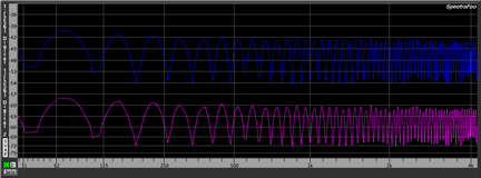
Comb filter on Pink Noise
The dreaded comb filter
You have probably heard this kind of filter in action — usually inadvertently. It crops up any time a microphone hears the same sound along two different paths. A good example of this is if someone is giving a lecture and speaking at a lectern. Usually the sound reinforcement system will have a gooseneck mic above the lectern. When the speech leaves the speaker’s mouth, it goes directly to microphone, but it also goes towards the lectern. It reflects off the hard surface of the lectern and then heads to the microphone. The sound that the reflected sound travels is longer than the direct path. So, the extra path length introduces a (short) delay relative to the direct signal. The total sound heard by the microphone has a comb filter.
The following sounds are (1) Pink noise without any time delay mixed in and (2) the same pink noise with a 0.01 sec time delay applied. This creates the Comb Filter effect.
Pink Noise
Pink Noise with Comb Filter
Other places this crops up is if you add plug-ins to a digital mixing system, or send audio out of your computer to be loop processed with analog gear, or if you multi-mic a source. The issue with plug-in latency has been (mostly) taken care of in modern digital audio products -- most DAWs now have integrated latency compensation for plug-in insert latencies, and sophisticated external DSP processors like Metric Halo’s own +DSP have internal latency compensation.
That being said, latencies introduced by external loops and multi-mic'ing of sources are not automatically compensated for by any products that we are aware of, and they can have a significant and detrimental effect on the quality of the sound and mixes you create.
The complexities of external loops we will leave for another tech page. The one thing about external loops is that you always know when you are using one because you actually have to set it up.
Multiple copies of related sources
Multi-mic'ing of sources is a bit more subtle; it can happen as a result of things you might do while recording that may not appear, on the surface, to introduce delays.
One example is if you record an instrument via a DI box (guitar or bass) and also record the same instrument with a microphone on the cabinet. Another common recording technique is to use close and far mics on an instrument. Finally, if you track with multiple mics, the bleed between the mics may be significant; when you multi-mic a drum kit, for example the bleed of one instrument (for example, the snare) into all the mics on the kit can be quite large, and the time delay between the snare mic and the other mics on the kit is on the order of a few tenths of a millisecond (top snare mic to bottom snare mic) to a few milliseconds (snare mic to overheads).
All of these time delayed copies can create significant comb filters in your mixes. The comb filters are subtle in the sense that you may not perceive them consciously unless you know what to listen for; instead you will just know that your mix doesn't sound great. It will sound hollow and ringy — generally disappointing. If you solo the individual instruments, they may sound great; but the overall mix sounds muddy and indistinct — just small.
Well, the good news is that once you understand the phenomena, and know what to look (and listen) for, it is actually pretty easy to fix. And fixing it is critical to ensuring that your mixes sound and feel professional. That’s why we include a short delay in every ChannelStrip instance; that way, whenever you need to introduce delays to compensate for recorded delays, the delay process is already part of your channel strip.
The general principle
The general principle of time-aligning multi-mic'ed sources is to identify the latest copy of the signal and then figure out how much you need to delay the other signals that have the same source. Once you have the delay offsets, you just insert the delays, and you are good to go.
Sounds easy, right? Well, as with everything worth doing, there are complications.
The biggest complication is that for may types of multi-mic situations, all the mics copies of multiple signals and it is not possible to actually align everything simultaneously. There are a number of techniques to deal with this, including:
Mic technique
Gating
EQ
Identifying the most critical elements
We’ll discuss some of these techniques below when we address the specific case of aligning drums. First we’ll discuss a simpler example.
A simple example
Let’s discuss the case of putting two microphones on a guitar cabinet (or an acoustic guitar for that matter). First off, why would we want to do this. Well the tone that the microphone hears way up close is very different than the tone further away. The close up tone tends to be bright and raw (and with cardioid mics will also have a bass-boost). The far mic tone tends to be smoother and more integrated, and also includes the sound of the room acoustics. Generally, a combination of those two tones with a judicious choice of mixing levels will yield an excellent recorded sound. The problem is that because of the time-of-flight delay to the far mic will cause the dreaded comb-filter when the two signals are mixed together.
Well, we know how to fix that right? We just delay the close mic signal by the appropriate amount so that it lines up with the far mic signal. Easy. But what is the proper delay? Well, that is the second complication. We can estimate it using the information about the speed of sound listed above.
Let’s say that the close mic is right on the guitar cabinet and that the far mic is 5 feet away from the cabinet. Then, the signal in the far mic is delayed from the close mic by
td = 5ft/(1137 ft/s) or td = 4.39 ms.
If you are recording at 44.1kHz sampling rate, this corresponds to
So, to summarize, the distance of 5 ft corresponds to just about 194 samples at 44.1kHz sample rate. This means that the signal in the far mic will be delayed from the close mic by 194 samples. If we want to align the two signals, we just dial in 194 sample delay in the close mic channel — this delays the close mic to align it with the far mic.
A bit more complicated
Now, the only problem with the approach above is that the speed of sound depends on temperature and pressure; so our estimate may not be that great. The best way of finding the appropriate time delay is to measure it directly. There are two ways to do that:
The simple way, if your recording software allows it, is to zoom way in on the waveform display and drag a selection from the beginning of a transient in close track to the beginning of the same transient in the far track. Then read out the delay using the time readout tools in your recording software.
If your recording software doesn’t provide support for reading out sample-level selections, or if you want to make the measurement most accurately, you can use a tool like the delay finder in SpectraFoo Complete to measure the precise delay between the two microphones.
A more complex example
OK. That was the simple case. Now let’s go back to the (much more difficult) problem of aligning a multi-mic'ed drum kit. As we described above, the problem when you are trying to time align a drum kit is that you have multiple mics, each of which is hearing multiple sources — and each source is a different distance from each mic. So, to make it more concrete, imagine you have a mic on the top of the snare, and you also have a mic on the hi-hat. The sound from the snare goes to the snare mic first, and then a delayed copy shows up in the hi-hat mic. No problem. But, unfortunately, the sound from the hi-hat goes to the hi-hat mic first and then a delayed copy winds up in the snare mic. So if you delay one mic, the other delayed signal will be delayed twice. In other words, its impossible!
So, since it isn't possible to get it perfect — instead we need figure out what is most important. The critical idea is that we want to try to minimize the overlap between the different microphones. This is different from the near and far mic case; we don't really want all the microphones to give us a representation of each signal in the drum kit; instead, the reason we are using multiple mics is to try to capture each element separately. So, if we are careful, we can limit the bleed into adjacent mics.
The first thing to do is to be careful with Mic technique; we want to use microphones that limit the bleed from the other elements of the drum kit. This can be accomplished with both mic selection and placement. Use of directional pick up patterns will limit bleed from elements that are outside the polar pattern of the microphones. When placing the mics, part of the placement selection is to use the drumkit as a baffle to isolate some of the mics from the other elements of the kit.
After applying care to the selection and placement of the microphones, we can also take into account the frequency spectrum of the various instruments. For example, the hi-hat and the snare have very different sets of characteristic frequencies associate with their timbres. As a result, you can utilize EQ to remove the bleed from the hi-hat from the top snare mic, and vice-versa.
In addition to EQ, since drums are patterned instruments, we can also utilize gating to try to limit the bleed from one element of the kit into the microphones for the elements of the kit. Since the elements of the kit have strong tonality, the sidechain feature of a gate (like the one in ChannelStrip) is incredibly useful. By adjusting the sidechain EQ you can control what signals cause the gate to open. By tuning it to the resonant frequencies of the drums, you will very effectively keep the other drums in the kit from opening the gate for that microphone.
So, if you apply the guidelines above, you will have limited amounts of overlap in the bleed between the mics. The primary mics that will still require a consideration of time-alignment are the following microphones:
Snare Top
Snare Bottom (if used)
Overheads
Hi-Hats
The reason that these microphones are the most important is that the overheads are pointed down at the instruments that the spot mics are listening to. Since both the snare and hi-hats have significant high-frequency energy, the comb-filter that will result from mixing the delayed signal is really significant.
So, to time align the kit, you want to figure out the following delays:
Snare Top → Overheads
Snare Bottom (if used) → Overheads
Hi-Hats → Overheads
and then delay the Snare Top, Snare Bottom, and Hi-Hats by the appropriate amounts so that all the sound is aligned with the signal that is in the overheads.
The following two drum mix samples were mixed without the Kick Drum for clarity sake so that you may better hear the subtle but apparent differences in the the mix. All pans and gains were identical. Only the snare and two over head mics were adjusted for zero time delay between the three sources.
Drum mix with no time alignment
Drum mix with time alignment
Give it a shot, you'll be shocked and happy with the results!
Expansion and gating are forms of dynamics control. Dynamics control is the process of automatically adjusting the volume control on an audio channel. The gain level of the channel is automatically adjusted by the process based upon the level of the audio signal passing through the processes detector. An expander is a dynamics control processor that lowers the volume of the signal when the overall level of the signal decreases. As a result, it tends to expand the dynamic range of the signal. A gate is a closely related process that essentially “cuts off” the incoming signal when the level drops below a predetermined level.
The question is, why would we want to make soft sounds softer? Well, it is often the case that the sound we want to record is contaminated by (sometimes much) lower level sounds from interfering sources. This can be bleed from other instruments when you are recording multiple instruments at once with multiple microphones. It could be background noise, like room noise or air handler noise. Or, it could be electrical interference like buzz or hum. If the recording environment is well constucted, none of these problems will arise, but often the recording environment is not ideal.
When the primary instrument (or voice) is at normal volumes, it masks the noise and makes the low level noise inaudible. So, when the sound level in the channel is high, you don't notice the noise, and it is not a problem. When the primary instrument (or voice) is not generating sound, the noise is no longer masked and can become both audible and irritating. If the channel also has a compressor or some other dynamics processor (like a guitar amplifier) in line (see the Compression tab to learn more about compressors), the very low-level noise signal may be amplified significantly, and as a result actually contribute a large amount of noise to the mix when the primary instrument in the channel is not generating sound.
The primary application
The expander/gate is a processor that allows you to automatically mute or attenuate the noisy low level signal in between the (relatively) loud parts that you want. If the expander/gate is placed in the signal chain before any compressor or limiter, it can be used to remove the low-level noise before it gets amplified by the compressor (or other dynamics processor like a guitar amp). Noise gates are quite effective when used as the first dynamics processor in a chain, and are relatively ineffective when used after a compresssor because the compressor removes the dynamic range that the gate uses to distinguish between the signal and the noise.
Basic controls
There are many different forms of exapanders and gates, all with different parameters. In this tech page, we will only address the most important parameters that you are likely to find on an expander/gate, and in fact, these are the parameters that you will find on the expander/gate that is part of ChannelStrip and MIOStrip. The primary parameters on a expander/gate are:
Threshold
Ratio
Attack
Release
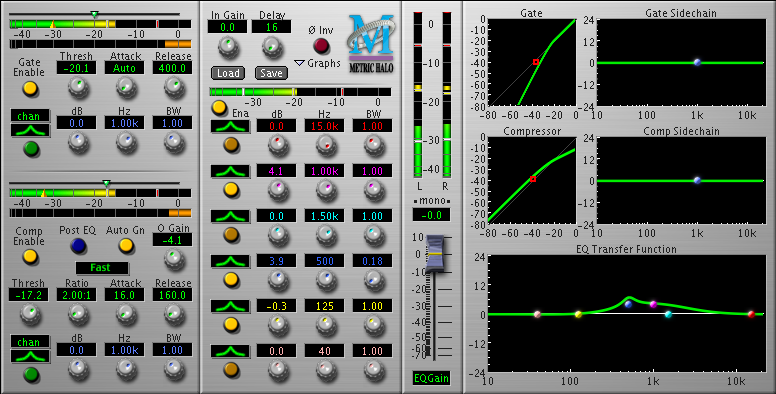
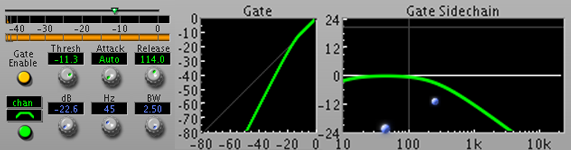
Channel Strip Gate Controls & Graph
The Threshold parameter allows you to select the level at which the gate will begin to function. When the detected level is below the threshold you select the gate will begin to attenuate the signal. If the detected level is above the selected threshold, the signal will pass through with no attenuation.
The Ratio parameter allows you to control the amount of attenuation applied to the input signal when the detector level is below the theshold. Higher ratios mean that the signal will be cut off more quickly as the detector level drops below the threshold. The gate in ChannelStrip has a fixed ratio — there is no control available for this parameter.
The Attack parameter controls the rate at which the detector tracks increases in signal level. For most applications you want the attack parameter to be instantaneous; this corresponds to a value of 0, or with ChannelStrip “auto”. By keeping the attack parameter set to allow for an instantaneous attack, the gate will release at very beginning of the sound that you want to pass through the gate. If the attack is set to have a longer time constant, the gate will have the effect of muting the inital transients of the sound that it lets through. This can be useful in a creative application of the gate; it can be used to make the attacks of a sound less sharp, and it can also be used to change the feel of the material that passes through it -- it has the effect of delaying the onset of impulsive sounds.
The Release parameter controls the rate at which the detector falls back from the measured peak level. It effectively controls the rate at which the gate closes as the sound level drops below the set threshold. For very impulsive sounds (like drums) it may be useful to set the release value quite low -- this has the effect of muting the channel in between the impulses of the drums, and it leads to a very dry sound, with no reverb and very short decays. If the release value is too low, it can lead to substantial distortion — in the extreme case, it can even sound broken. Large values of the release parameter will serve to cause the gate to “skip” over short segments of sound that are below the threshold. Longer release times may be appropriate for use on vocal mics; this will have the effect of muting the mike on long pauses, but not chopping up the silences between words. For guitars and other similar instruments, intermediate values are most appropriate; tune the release to taste — you will generally be shooting to have the release time short enough to mute the instrument while it is not playing but long enough that the muting action sounds like a very smooth fade as opposed to a rough cut-off of the sound.
Other applications
As we alluded to in the preceding paragraphs about the parameters of the expander/gate, there are other applications besides noise-reduction.
By carefully adjusting the attack and release parameters of the expander/gate, you can achieve many creative effects including:
reverb reduction
shortening the decay characterisics of impulsive instruments (such as drums)
changing the rythmic feel of existing tracks
synthesising elements from a triggering source
The last application listed relies on having a sidechain key input. This application allows you to open the gate via different souce than the sound passing through the gate. One way that this is used is adding an EQ'ed noise source to a snare drum sound every time the snare hits. This is extremely useful if the recorded snare sound is weak.
As an example, here are some drum mixes that show the before and after results that can be achieved with the ChannelStrip plugin:
Drum mix with no processing
Drum mix with processing (gate, comp, EQ)
If the gate has a sidechain, the detector can be driven with a different signal than the signal that is being gated. This allows you to accomplish all sorts of interesting things that would be virtually impossible otherwise. Basically, a gate with a sidechain decouples the level detector from the input signal. When people say “sidechain”, they usually mean one of two things:
One meaning of sidechain is an independent input feeds the detector, and can be connected to any arbitrary signal source. When the compressor has this kind of sidechain it can be used to implement things like the trigger described above.
The second meaning of sidechain is that the gate has an additional integrated signal processor between the input signal and the detector. This signal processor is usually an EQ, and it allows you to make the gate react in a frequency-sensitive way.
The expander/gate in ChannelStrip and MIOStrip actually implement both types of sidechains; the sidechain can be fed from an external key input or the input signal and the processors integrate a sidechain EQ before the detector.
Having an EQ integrated into the detector is particularly useful, because it allows you to make the gate more or less sensitive to certain frequencies. This can be used, for example, to make the gate only open for the signal of interest, while ignoring other (possible quite loud) sound sources that appear in the channel.
Careful application of the gate as a signal processor can make your mixes crisper and tighter, with (substanitally) less noise and grunge while still revealing the low-level details. Overapplication of the gate can make your mixes dry and lifeless or even distorted. As with most signal processors, it requires experience and taste, but once you get it right, you will be shocked at the difference.
The word “compression” is commonly used to describe two very different processes:
Digital Audio Data Compression (e.g. MP3, AAC, etc.)
Audio Level Compression (Dynamics Control)
In this context we are talking about the second process — dynamics control. Dynamics control is the process of automatically adjusting the volume control on an audio channel. The gain level of the channel is automatically adjusted by the process based upon the level of the audio signal passing through the processes detector. A compressor is a dynamics control processor that lowers the volume of the signal when the overall level of the signal increases. As a result, it tends to moderate or compress the dynamic range of the signal.
Compressors have a huge number of applications. They can be used as so-called “leveling-amplifiers” or automatic gain controls, which tend to keep the overall volume of the material constant. They can be used as limiters, which ensure that no matter what the level of the input signal is, the output level will never go above a specified level. They can be used to simply limit the overall dynamics of the signal, or they can be used to creatively change the timbre of the signal.
Most of the various applications can be accomplished by adjusting the parameters of the compressor; some applications depend on how the compressor is implemented. Depending on the compressor’s implementation, it may not be possible to actually achieve all modes of operation by adjusting the parameters. For example, many compressors (including the one in ChannelStrip) are not terribly effective as limiters; the limiting process may require a different approach to computing and applying the gain than a specific compressor provides.
Compressor parameters
Compressors have a wide variety of control parameters, but the most common ones are:
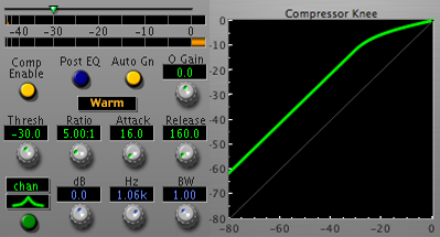
Channel Strip Compressor Controls & Graph
Threshold
Ratio
Knee
Character
Attack Time
Release Time
Input Gain
Makeup Gain
Auto gain
Output Ceiling
These parameters tend to be highly interactive, but let’s examine each one in turn.
Threshold allows you to set the level at which the detector will begin to cause the compressor to reduce the gain of the signal that is running though it. Basically, if the input signal (or the detector source if you are using a compressor with a side chain) is below the threshold level, the gain cell in the compressor will not change the signal level (but see “Knee” below for some more details). If the detector level is above the threshold, the compressor will compute an attenuation (in other words, a gainreduction) to apply to the signal based upon the detector level, the ratio and the knee parameters. The threshold sets where the action starts; the other parameters control what happens once the compression is in effect.
Ratio allows you to control the ratio of the change of input level to the change of output level, when the signal is above the threshold. This ratio is specified in dB. So, for a standard compressor, the ratio for the compressor below threshold is 1:1. This means that for every dB the input signal increases, the output signal also increases 1 dB. Once the detector goes above threshold, the ratio applied is the one that you set with the ratio control. This ratio only applies to the part of the signal that is above the threshold. So, if, for example, the ratio is set to 2:1, and the input signal is 2 dB above the threshold, the output signal will have only increased 1 dB above the threshold. To make this more concrete, let’s look at a hypothetical setting. Assume the compressor threshold is set to -30dB, and the ratio is set to 5:1. Let’s figure out what the output level will be for a variety of input levels:
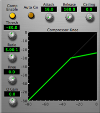
Hard Knee Compressor
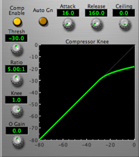
Soft Knee Compressor
If the input level is -40 dB, the level is below threshold, and the output level will be -40 dB.
If the input level is -30 dB, the level is just at threshold, and the output level will be -30 dB.
If the input level is -20 dB, the level is 10 dB higher than the threshold, and the output level will be -30 dB + (10dB/5) or -32 dB. In other words the compressor will only let the output go up 1dB for each 5 dB the input goes above the threshold.
The ratio allows you to control by how much the dynamics will be limited. The threshold lets you control at what point in the signal level the effect will begin to act.
Brick Wall Limiter
Many compressors only have a limited number of ratio settings. Often limiters only have one setting — ∞:1. This ratio is known as a brick-wall limiter, because the output level never goes above the threshold. For compression, generally ratios between 1:1 and 20:1 are useful. If the compressor has a soft knee, higher ratios can often be used to great effect.
Knee is a parameter that only appears on some compressors. Sometimes it is labeled as Soft/Hard Knee. Sometimes it is a continuous control that allows you to morph between soft and hard knees (for example the knee control in the MIO Compressor). Some compressors only have hard knees. Some only have soft knees (like ChannelStrip). A hard-knee compressor is one in which the compression ratio transitions from 1:1 to the set ratio abruptly at the threshold point. A soft knee compressor gradually transitions from the 1:1 ratio to the set ratio as the level transitions past the threshold. Some soft knee compressors (like the MIO Compressor) have a 1:1 ratio below the threshold and only start to apply gain reduction after the input level goes above the threshold. Other soft knee compressors (like ChannelStrip) actually start to transition from the 1:1 ratio below the threshold. This means that these compressors will actually start compressing the signal below the threshold. It is part of the character of those processes. Soft knee compressors tend to have a smoother sound; this can be very appropriate for certain types of compression — particularly when you don't want to “hear” the compressor working. Hard knees can be very effective when you are using the compressor as a signal transformation tool where you do want to hear the effects of the compressor.
Many compressors have a Character control although it may not be labelled as such. Sometimes it will be labelled as Opto or some such semi-descriptive name. The ChannelStrip compressor has an explicit Character control. These types of controls have an effect on the inner workings of the compression algorithm and usually have a substantial effect on both the distortion introduced by the compressor and the reactivity of the compressor. Usually, this is not a parameter that can be understood — instead, it is best to think of it as something that needs to be experienced to understand what effect it will have. We have tried to make the Character control on ChannelStrip descriptive; the setting names should give you some idea of the effects of changing this control.
Attack Time allows you to control how quickly the detector will react to changes in the input level. When the attack time is set to a small value, the detector will react quickly to increases in the input level. This will allow it to compress transients quickly, but will tend to increase the distortion introduced by the processor. Short attack times are consistent with using a compressor in a limiting or an effect application. Longer attack times will allow short transients to pass through the compressor unaltered; this kind of setting is more appropriate when using a compressor in a leveling application; it makes it so that the compressor will react to longer term changes in levels and not try to follow the short-term dynamics of the material.
Release Time allows you to control how quickly the detector falls back from the peak detected levels. When the release time is short, the compressor will remove gain reduction quickly; in other words it will only tend to act on the short transient high-level material, and will quickly return to no gain reduction as the signal level decreases. This can be used along with makeup gain to significantly reduce the dynamics of the signal and as a result increase the overall loudness of the signal. If the release time is too short, the compressor will actually follow the shape of the waveform and will introduce significant audible distortion. If you are using the compressor in a leveling application, longer release times are appropriate (even into the seconds), as you don't want to introduce distortions or abrupt level changes. Again, short release times will tend to greatly effect the timbre of the signal; as a result, you will tend to want to use shorter release times when you are using a compressor as an effect to change the basic nature of the signal being processed. For example, both short attack and release times are appropriate for use on drum signals as they tend to moderate the initial short transient, and bring up the tone and detail of the body of the sound as the drum hit decays away.
Input Gain is available on some compressors, and it applies gain to the signal before the detector and gain cell of the compressor. It is often called "drive" on the compressors that offer it as a parameter. Usually compressors with a drive control have a fixed threshold and knee, and the amount of compression applied is controlled by how hard the signal is driven into the compressor.
Makeup Gain allows you to set the gain that is applied to the signal after the compression has been applied. Since the compressor reduces the gain of the signal above the threshold, the overall signal level drops as it passes through the compressor. While this is sometimes what you are after (for example if you are trying to level the program material to a consistent level — say, for use as background music in a café), often you want to use the compressor to reduce the dynamic range of the material without reducing the peak level. This has the effect of increasing the loudness of the material because the dynamic range is compressed up to the top of the range, instead of limited to the lower portion of the range. In order to do this, you must apply gain to the compressed signal to move it to the top of the range. See also Auto gain below.
Auto gain is available on some compressors (including ChannelStrip and the MIO Compressor), and when enabled, will cause the compressor to automatically estimate the proper make-up gain required to make it so that full-scale input levels generate full-scale output levels. In the Metric Halo compressors, the Makeup Gain control is still active; it is used to trim the output level from the automatically computed gain.
Output Ceiling is generally only available on limiters. It specifies the absolute maximum level of the output signal from the limiter. This is useful to ensure that the output signal level does not exceed some specified safety level.
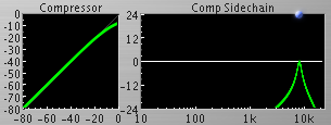
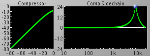
Its all in the sidechain!
As with the gate, one of the most powerful aspects of a compressor is its sidechain. If the compressor has a sidechain, the detector can be driven with a different signal than the signal that is being compressed. This allows you to accomplish all sorts of interesting things that would be virtually impossible otherwise. Basically, a compressor with a sidechain decouples the level detector from the input signal. When people say “sidechain”, they usually mean one of two things:
One meaning of sidechain is an independent input feeds the detector, and can be connected to any arbitrary signal source. When the compressor has this kind of sidechain it can be used to implement things like duckers.
The second meaning of sidechain is that the compressor has an additional integrated signal processor between the input signal and the detector. This signal processor is usually an EQ, and it allows you to make the compressor react in a frequency-sensitive way.
The compressors in ChannelStrip and MIOStrip actually implement both types of sidechains; the sidechain can be fed from an external key input or the input signal and the processors integrate a sidechain EQ before the detector.
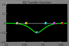
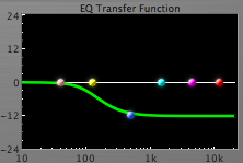
Having an EQ integrated into the detector is particularly useful, because it allows you to make the compressor more or less sensitive to certain frequencies. This can be used, for example, to make the compressor act as a de-esser. By accentuating the cluster of frequencies up in the 8-12kHz region (where the ess sound of sibilance is most prevalent), you can configure the compressor to lower the volume of sounds that have substantial energy in the "ess" range. Similarly, you can use the sidechain EQ to enhance the response to the low end when compressing bass or bass drums. Another useful application of side-chain EQ is to cut the response of the compressor to a range of frequencies; one aspect of compression is that it tends to dull the signal; often rolling off the high-end of the sidechain (with a high cut filter) can provide useful compression of the low-end without dulling the high-end.
De-ess at 8KHz
De-Ess & Compression at 8KHz
The above examples show the differences the filter choice of the side chain detector can have. The 1st example (left) has a Bandpass filter in the sidechain detector. While the 2nd example (right) has a peaking filter in the sidechain detector. The compressor settings for both examples are identical but the output will be vastly different.
Operate all the controls at once...
As with many audio processes, compression is often best understood by “operating all the knobs at once”. The information in this guide should get you started, but don't be afraid to experiment and adjust the parameters to get a real sense of the effect that they have on the audio. A great place to start is by loading the presets in ChannelStrip to see what settings we have selected for different effects. The presets work as a great starting point; you will find that you can get close to the sound you are looking for with the presets, and then tweak the parameters to achieve your goal!
In order to understand equalization, we first need to have a short discussion about the nature of sound. As you may know, sound is a pressure wave that (usually) travels through air. Sound causes the pressure of air to vary about the standard one atmosphere of pressure. The variation of the pressure of the air causes the tympanic membrane in your ear to move, which transmits the movements into your inner ear. Your inner ear has a sophisticated spectrum analyzer that more or less breaks down the sound into its component frequencies. Because this is our fundamental mechanism for perceiving sound everything about the our perception of sound can be understood in terms of the frequencies of harmonic waves.
Because of the nature of the spectrum analyzer in our ears, what we perceive as pitch or tone (at least to a first approximation) maps directly to the frequency of pure sine waves. The frequency of a wave is simply the rate at which it repeats. A pure sine wave is a wave that only has one component pitch, and no overtones. All possible waveshapes can be created by combining multiple (perhaps an infinite number) sine waves with different amplitudes and phases. Most musical waves (and to a lesser extent speech) are composed of harmonic waves — waves composed of a definite fundamental tone and partial overtones that are integer multiples of the fundamental pitch (these are called harmonics). The timber of the sound is controlled by the relative levels of the overtones.
So, basically, we now understand that the timbre of a sound is (mostly) characterized by its amplitude as function of frequency. This amplitude will also change with time, and the amplitude as a function of time may be different (and probably will be) for each different frequency in the sound. This is why the timbre of a sound changes over time.To make this more concrete, think about how a single note on a piano changes over time; when the note is first struck, in addition to the tonal part, it also has an impulsive part — the strike of the hammer on the string. This is called the attack, and there are many frequencies represented — both harmonic and non-harmonic components. The non-harmonic components quickly die away because they are not supported by the resonance of the stretched string. The note then enters the sustain phase, where it is almost completely composed of the fundamental tone and its overtones. The shape of the amplitude of the overtones is characteristic of the piano, and is what makes it sound like a piano. As the sound begins to decay, it turns out that the higher overtones decay away faster with time than the lower overtones. So, as the note sustains, the overall volume decreases and the timbre becomes darker, eventually becoming something close to a pure tone (although the overall volume may be so low at this point that it is hard to hear). Now a piano is actually more complex than this; energy may actually move from one overtone to another during the decay, and this is a big part of the beauty of the instrument.
OK, but what about equalization?
So, that’s all very interesting, but what does it have to do with equalization? Well, bear with us for a few more sentences while we explain why it is called equalization, and then we can get to the point.
The original equalizers were invented for telecommunications applications. The problem was that when you drive a long, long wire with the analog signal from a telephone, there are frequency dependent losses in the signal; the cable attenuates the high end more than it does the low end. As a result, the telephone signal was rolled off at the other end of the cable making it sound very dark, and potentially difficult to understand. Since the cable changed the frequency content of the signal, a circuit was devised to equalize the levels as a function of frequency. Thus the term “equalizer”. In fact this was done as a pre-equalizer, where the high-end of the signal was boosted before the signal was sent across the cable, as this approach did not require the amplification of high-frequency noise at the far end of the cable.
This approach to equalization is still an important application of the equalizer today; for example, this is precisely how equalizers are used in the system control units in live sound reproduction systems; an EQ is constructed so that when the pre-Equalized signal is processed by the acoustic environment of the venue, the net effect is to have a (relatively) flat response as a function of frequency in the room.
Production EQ
OK — now we are ready to talk about the EQ that you find in the studio, or on a console, or in a plug-in like ChannelStrip.
In the text above, we described how the timbre of an instrument or a voice was (mostly) characterized by its amplitude as a function of frequency. So, if we wish to change the timbre of a signal (instrument, voice, whatever), the first place we are going to want to start is by changing the amplitude as a function of frequency. This is precisely what an equalizer does. But instead of using it to equalize the overall response of a system, we are going to use it to make creative changes to an instrument, a voice or an entire mix.
The original equalizers used for this purpose were so-called “Tone Controls.” These were usually composed of three fixed bands:
a low shelf
a midrange presence filter
a high shelf
Low Shelf Filter
Presence Filter
High Shelf Filter
The bands all overlapped, and you could adjust the gain on each band to boost or cut the low end, mid-range, or high end, respectively. The thing is — that does not provide a lot of control. Sometimes the range of frequencies you want to change is quite narrow; and often the center of the range that you want to change is not where the center of the EQ band is. Early British made commercial mixing consoles added another band, and the design had a very nice set of center frequencies and bandwidths; this was the so-called “British EQ” and was very useful for music production, but still lead to the situation where sometimes you could not quite get the EQ that you needed to adjust the timbre as you desired. This fact lead to the invention of the Parametric EQ.
The parametric EQ provides independent parameters for the center frequency, the bandwidth and the boost or cut of the EQ band — thus the name “Parametric” EQ.
Modern EQs are either partially-parametric or fully-parametric. A partially parametric EQ has one or more bands of parametric EQ with additional bands that are fixed function as shelves or high and low cut filters. A fully-parametric EQ, like the ones in ChannelStrip and the MIO+DSP package have fully parametric bands for each available band in the EQ. Any band can be made into any filter type, and all bands have full parametric range for all the parameters. This makes the EQ very flexible.
Perhaps it would be a good idea to explain what the different filter types are. There are a number of standard filter types that are available in a fully parametric EQ:
Peaking or Presence filter
High Shelf filter
Low Shelf filter
High cut (or alternatively low pass) filter
Low cut (or alternatively high pass) filter
Band pass filter
Peak Cut Filter
High Shelf Filter
Low Shelf Filter
High Cut Filter
Low Cut Filter
Band Pass Filter
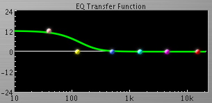
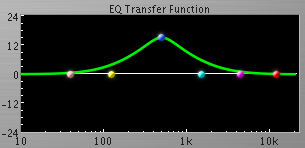
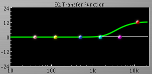
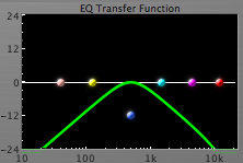
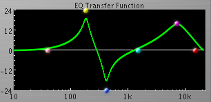
The Peaking (or presence) filter is the original “parametric” EQ filter type. It allows you to boost or cut a range of frequencies around the frequency that you specify, by the amount that you specify. The boost or cut will be the amount that you specify at the center frequency and will taper back to no change on either side of the center frequency. The bandwidth (or Q) parameter controls how quickly it will taper back to no change. Since the EQ in ChannelStrip automatically graphs the change in amplitude as a function of frequency as you change the parameters, you can quickly get a sense of what the various parameters really mean by enabling one band in the EQ, changing the parameters and watching how the response graph changes. Some Peaking filters (like the ones in ChannelStrip) become quite resonant when you set the gain high. This can be used quite effectively to create resonant sounds where they were originally missing from the recorded sound. Check out the Drum tuning example below for more info.
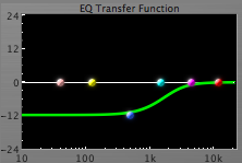
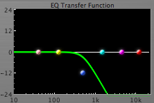
The Shelving filters (High and Low) are characterized by adjusting the amplitudes of all the frequencies above (or below in the case of the low shelf) the characteristic frequency that you set. The gain (or cut) is applied as you set it. Below the characteristic frequency you set (or above in t the case of the low shelf), the gain tapers back to no change. On the ChannelStrip EQ, the bandwidth control adjusts the slope of the shelf, and the amount of peak and dip exhibited at the transition. Again, the best way to understand this is to play with the ChannelStrip UI and look at the graph as you change the parameters.
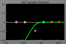
The High and Low cut filters simply attenuate the frequencies above (or below for the low pass case) the frequency you set. The gain and bandwidth have no effect on these filter types. Some EQs allow you to control the slope of the cutoff, but the filters in ChannelStrip don’t have that kind of control available. If you need to make the cut-off steeper, you can stack multiple bands at the same frequency. Low cut filters are useful for removing DC and rumble. High cut filters are often useful in side-chains and to control the high end of signals. That being said, often high shelf filters are more appropriate for adjusting the high-end timbre of a signal.
The Band pass filter is a combination of the High and Low cut filters. This kind of filter attenuates the frequencies both above and below the band that you have selected. The frequency control selects the center of the band that is allowed to pass through the EQ, and the bandwidth controls, well, the width of the band that is passed. This type of filter is often used in a dynamics processor sidechain to limit the range of frequencies that the processor detects.
EQ in use
The applications of a good parametric EQ are literally limitless. From subtle adjustments in Mastering to huge folding, spindling and mutilating EQ for mixing and sound design, you can literally manufacture sounds from (almost) nothing, fix terrible tracks, or just make things fit.
If you check out a variety of recording books, magazine articles, and websites, you’ll find a myriad suggestions about the frequency ranges of different instruments and timbres. When you get to work with your tracks and your EQ, you’ll find out that most of them are wrong, or don't tell you the whole story. It is very difficult to characterize the precise nature of what frequency range corresponds to what timbre. You’ll find (as you gain experience) that it is often the relative balance of frequencies that count; sometimes it is better to cut the midrange than to boost the highs. Experimentation is key; starting from the presets in ChannelStrip is a great way to learn how to configure the EQ to achieve specific goals. You will often find that the preset will get most of the way there — then tweak the parameters to dial in the result you are looking for.
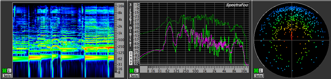
As we said above, it is very difficult to provide rules of thumb about frequency ranges and timbres. The most effective way we have found to zero in on the critical frequencies and the building blocks of the timbres you are working with is to use a tool like SpectraFoo to look at the spectral structure of the tracks and mixes you are working with. Since SpectraFoo shows you the evolving timbral structure synchronized with the audio you are listening to, you can quickly learn and identify the aspects of the sound that you want to enhance or decrease.
Example SpectraFoo Instruments
One thing that you will quickly find as you begin to mix multiple instruments is that quite often individual instruments will sound great by themselves, but when you mix them together, they tend to obscure each other. One of the trickiest aspects of mixing is figuring out how to create a “space” in the mix for each of the instruments and voices. Often you can create space by panning the elements. But sometimes you find that the frequency overlap of the elements makes both elements muddy or indistinct. This will often happen between bass and drums or between guitar and vocals. In these cases, you can often use EQ to carve holes in the spectrum of one or more of the overlapping elements to make room. While the EQ may make each element on its own sound worse, the combined mix sounds better. Again, a tool like SpectraFoo can be incredibly helpful.
Taking advantage of resonance
Parametric EQs that are capable of implementing resonant filters (like ChannelStrip) are able to perform a really cool trick with drum tracks. Every drum in a drum kit has a natural resonant frequency. While drums are impulsive, anharmonic instruments, if the drums are tuned properly, the decay of each hit on each drum has a different resonant frequency. It is the relative tuning of the drums (the rack and floor toms, the snare and the bass drum) that define the timbre and character of the drum track; the drummer provides the rhythm and the pattern. Often, you'll find that the drums are not tuned properly when you record them. Or that in the end, you would like to have them tuned differently than they were when the recording was made. The latter case may actually happen a lot when you are using sampled drums.
Drum Re-Tune Filter
The resonant character of the peaking filters can actually be used to "re-tune" the drums after they have been recorded. The basic approach is to find the resonant frequency of the drum as recorded (you can do this easily with SpectraFoo or less easily by sweeping a narrow band filter) and place a narrow notch (peaking filter with negative gain) filter at the resonant frequency to remove the original ring of the drum, and then place another narrow peaking filter with 18-24dB of gain at the new resonant frequency. You may need to place multiple notches. This is often very useful when working with a recording of a choked snare or kick (bass) drum that does not resonate very much at all. You'll find that 50-80 Hz works really well for bass drums and 100-120 Hz works well for the snare. If the snare sounds really “pingy” you'll find that a slightly wide notch at about 180 Hz will tend to take the ping out — and you'll probably want to replace it with a somewhat lower resonance. Of course, we already have some presets in ChannelStrip that provide good starting points for retuning drums; you’ll have to tune them to the details of you specific drum tracks.
Here are some example drum tracks that show a kick drum and snare drum that have been "re-tuned" with the ChannelStrip Plugin:


 Drum Re-Tune Filter